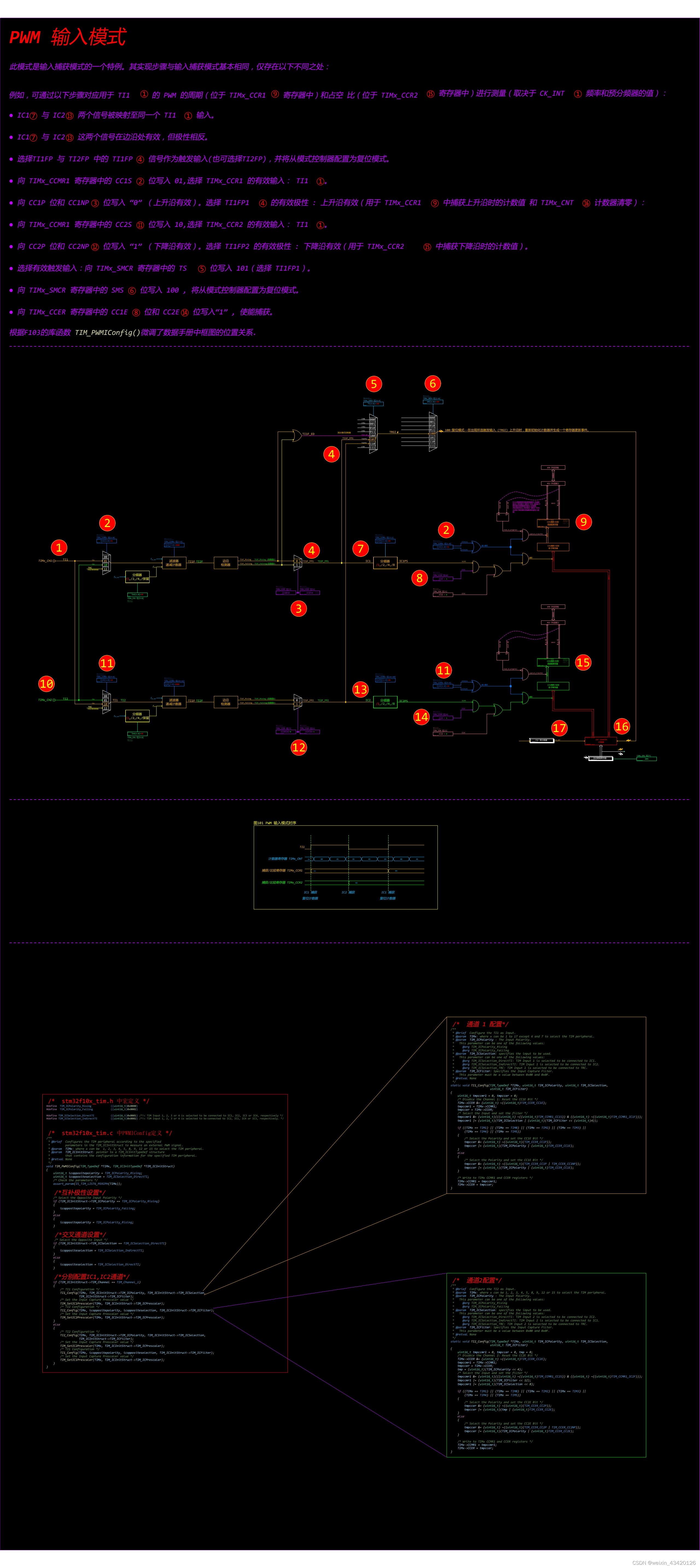
PWM 输入模式
此模式是输入捕获模式的一个特例。其实现步骤与输入捕获模式基本相同,仅存在以下不同之处:
例如,可通过以下步骤对应用于 TI1① 的 PWM 的周期(位于 TIMx_CCR1⑨ 寄存器中)和占空 比(位于 TIMx_CCR2⑮ 寄存器中)进行测量(取决于 CK_INT① 频率和预分频器的值):
● IC1⑦ 与 IC2⑬ 两个信号被映射至同一个 TI1① 输入。
● IC1⑦ 与 IC2⑬ 这两个信号在边沿处有效,但极性相反。
● 选择TI1FP 与 TI2FP 中的 TI1FP④ 信号作为触发输入(也可选择TI2FP),并将从模式控制器配置为复位模式。
● 向 TIMx_CCMR1 寄存器中的 CC1S② 位写入 01,选择 TIMx_CCR1 的有效输入: TI1①。
● 向 CC1P 位和 CC1NP③ 位写入 “0” (上升沿有效)。选择 TI1FP1④ 的有效极性 : 上升沿有效(用于 TIMx_CCR1⑨ 中捕获上升沿时的计数值 和 TIMx_CNT⑯ 计数器清零):
● 向 TIMx_CCMR1 寄存器中的 CC2S⑪ 位写入 10,选择 TIMx_CCR2 的有效输入: TI1①。
● 向 CC2P 位和 CC2NP⑫ 位写入 “1” (下降沿有效)。选择 TI1FP2 的有效极性 : 下降沿有效(用于 TIMx_CCR2⑮ 中捕获下降沿时的计数值)。
● 选择有效触发输入:向 TIMx_SMCR 寄存器中的 TS⑤ 位写入 101(选择 TI1FP1)。
● 向 TIMx_SMCR 寄存器中的 SMS⑥ 位写入 100 , 将从模式控制器配置为复位模式。
● 向 TIMx_CCER 寄存器中的 CC1E⑧ 位和 CC2E⑭ 位写入“1” , 使能捕获。
根据F103的库函数TIM_PWMIConfig()微调了数据手册中框图的位置关系.
TIM_PWMIConfig()函数
/*	stm32f10x_tim.h 中宏定义 */
#define  TIM_ICPolarity_Rising             ((uint16_t)0x0000)
#define  TIM_ICPolarity_Falling            ((uint16_t)0x0002)#define TIM_ICSelection_DirectTI           ((uint16_t)0x0001) /*!< TIM Input 1, 2, 3 or 4 is selected to be connected to IC1, IC2, IC3 or IC4, respectively */
#define TIM_ICSelection_IndirectTI         ((uint16_t)0x0002) /*!< TIM Input 1, 2, 3 or 4 is selected to be connected to IC2, IC1, IC4 or IC3, respectively. *//*	stm32f10x_tim.c 中PWMIConfig定义 */
/*** @brief  Configures the TIM peripheral according to the specified*         parameters in the TIM_ICInitStruct to measure an external PWM signal.* @param  TIMx: where x can be  1, 2, 3, 4, 5, 8, 9, 12 or 15 to select the TIM peripheral.* @param  TIM_ICInitStruct: pointer to a TIM_ICInitTypeDef structure*         that contains the configuration information for the specified TIM peripheral.* @retval None*/
void TIM_PWMIConfig(TIM_TypeDef *TIMx, TIM_ICInitTypeDef *TIM_ICInitStruct)
{uint16_t icoppositepolarity = TIM_ICPolarity_Rising;uint16_t icoppositeselection = TIM_ICSelection_DirectTI;/* Check the parameters */assert_param(IS_TIM_LIST6_PERIPH(TIMx));/*互补极性设置*//* Select the Opposite Input Polarity */if (TIM_ICInitStruct->TIM_ICPolarity == TIM_ICPolarity_Rising){icoppositepolarity = TIM_ICPolarity_Falling;}else{icoppositepolarity = TIM_ICPolarity_Rising;}/*交叉通道设置*//* Select the Opposite Input */if (TIM_ICInitStruct->TIM_ICSelection == TIM_ICSelection_DirectTI){icoppositeselection = TIM_ICSelection_IndirectTI;}else{icoppositeselection = TIM_ICSelection_DirectTI;}/*分别配置IC1,IC2通道*/if (TIM_ICInitStruct->TIM_Channel == TIM_Channel_1){/* TI1 Configuration */TI1_Config(TIMx, TIM_ICInitStruct->TIM_ICPolarity, TIM_ICInitStruct->TIM_ICSelection,TIM_ICInitStruct->TIM_ICFilter);/* Set the Input Capture Prescaler value */TIM_SetIC1Prescaler(TIMx, TIM_ICInitStruct->TIM_ICPrescaler);/* TI2 Configuration */TI2_Config(TIMx, icoppositepolarity, icoppositeselection, TIM_ICInitStruct->TIM_ICFilter);/* Set the Input Capture Prescaler value */TIM_SetIC2Prescaler(TIMx, TIM_ICInitStruct->TIM_ICPrescaler);}else{/* TI2 Configuration */TI2_Config(TIMx, TIM_ICInitStruct->TIM_ICPolarity, TIM_ICInitStruct->TIM_ICSelection,TIM_ICInitStruct->TIM_ICFilter);/* Set the Input Capture Prescaler value */TIM_SetIC2Prescaler(TIMx, TIM_ICInitStruct->TIM_ICPrescaler);/* TI1 Configuration */TI1_Config(TIMx, icoppositepolarity, icoppositeselection, TIM_ICInitStruct->TIM_ICFilter);/* Set the Input Capture Prescaler value */TIM_SetIC1Prescaler(TIMx, TIM_ICInitStruct->TIM_ICPrescaler);}
}
TI1_Config (函数)
/*	通道 1 配置*/
/*** @brief  Configure the TI1 as Input.* @param  TIMx: where x can be 1 to 17 except 6 and 7 to select the TIM peripheral.* @param  TIM_ICPolarity : The Input Polarity.*   This parameter can be one of the following values:*     @arg TIM_ICPolarity_Rising*     @arg TIM_ICPolarity_Falling* @param  TIM_ICSelection: specifies the input to be used.*   This parameter can be one of the following values:*     @arg TIM_ICSelection_DirectTI: TIM Input 1 is selected to be connected to IC1.*     @arg TIM_ICSelection_IndirectTI: TIM Input 1 is selected to be connected to IC2.*     @arg TIM_ICSelection_TRC: TIM Input 1 is selected to be connected to TRC.* @param  TIM_ICFilter: Specifies the Input Capture Filter.*   This parameter must be a value between 0x00 and 0x0F.* @retval None*/
static void TI1_Config(TIM_TypeDef *TIMx, uint16_t TIM_ICPolarity, uint16_t TIM_ICSelection,uint16_t TIM_ICFilter)
{uint16_t tmpccmr1 = 0, tmpccer = 0;/* Disable the Channel 1: Reset the CC1E Bit */TIMx->CCER &= (uint16_t) ~((uint16_t)TIM_CCER_CC1E);tmpccmr1 = TIMx->CCMR1;tmpccer = TIMx->CCER;/* Select the Input and set the filter */tmpccmr1 &= (uint16_t)(((uint16_t) ~((uint16_t)TIM_CCMR1_CC1S)) & ((uint16_t) ~((uint16_t)TIM_CCMR1_IC1F)));tmpccmr1 |= (uint16_t)(TIM_ICSelection | (uint16_t)(TIM_ICFilter << (uint16_t)4));if ((TIMx == TIM1) || (TIMx == TIM8) || (TIMx == TIM2) || (TIMx == TIM3) ||(TIMx == TIM4) || (TIMx == TIM5)){/* Select the Polarity and set the CC1E Bit */tmpccer &= (uint16_t) ~((uint16_t)(TIM_CCER_CC1P));tmpccer |= (uint16_t)(TIM_ICPolarity | (uint16_t)TIM_CCER_CC1E);}else{/* Select the Polarity and set the CC1E Bit */tmpccer &= (uint16_t) ~((uint16_t)(TIM_CCER_CC1P | TIM_CCER_CC1NP));tmpccer |= (uint16_t)(TIM_ICPolarity | (uint16_t)TIM_CCER_CC1E);}/* Write to TIMx CCMR1 and CCER registers */TIMx->CCMR1 = tmpccmr1;TIMx->CCER = tmpccer;
}
TI2_Config (函数)
/*	通道2配置*/
/*** @brief  Configure the TI2 as Input.* @param  TIMx: where x can be 1, 2, 3, 4, 5, 8, 9, 12 or 15 to select the TIM peripheral.* @param  TIM_ICPolarity : The Input Polarity.*   This parameter can be one of the following values:*     @arg TIM_ICPolarity_Rising*     @arg TIM_ICPolarity_Falling* @param  TIM_ICSelection: specifies the input to be used.*   This parameter can be one of the following values:*     @arg TIM_ICSelection_DirectTI: TIM Input 2 is selected to be connected to IC2.*     @arg TIM_ICSelection_IndirectTI: TIM Input 2 is selected to be connected to IC1.*     @arg TIM_ICSelection_TRC: TIM Input 2 is selected to be connected to TRC.* @param  TIM_ICFilter: Specifies the Input Capture Filter.*   This parameter must be a value between 0x00 and 0x0F.* @retval None*/
static void TI2_Config(TIM_TypeDef *TIMx, uint16_t TIM_ICPolarity, uint16_t TIM_ICSelection,uint16_t TIM_ICFilter)
{uint16_t tmpccmr1 = 0, tmpccer = 0, tmp = 0;/* Disable the Channel 2: Reset the CC2E Bit */TIMx->CCER &= (uint16_t) ~((uint16_t)TIM_CCER_CC2E);tmpccmr1 = TIMx->CCMR1;tmpccer = TIMx->CCER;tmp = (uint16_t)(TIM_ICPolarity << 4);/* Select the Input and set the filter */tmpccmr1 &= (uint16_t)(((uint16_t) ~((uint16_t)TIM_CCMR1_CC2S)) & ((uint16_t) ~((uint16_t)TIM_CCMR1_IC2F)));tmpccmr1 |= (uint16_t)(TIM_ICFilter << 12);tmpccmr1 |= (uint16_t)(TIM_ICSelection << 8);if ((TIMx == TIM1) || (TIMx == TIM8) || (TIMx == TIM2) || (TIMx == TIM3) ||(TIMx == TIM4) || (TIMx == TIM5)){/* Select the Polarity and set the CC2E Bit */tmpccer &= (uint16_t) ~((uint16_t)(TIM_CCER_CC2P));tmpccer |= (uint16_t)(tmp | (uint16_t)TIM_CCER_CC2E);}else{/* Select the Polarity and set the CC2E Bit */tmpccer &= (uint16_t) ~((uint16_t)(TIM_CCER_CC2P | TIM_CCER_CC2NP));tmpccer |= (uint16_t)(TIM_ICPolarity | (uint16_t)TIM_CCER_CC2E);}/* Write to TIMx CCMR1 and CCER registers */TIMx->CCMR1 = tmpccmr1;TIMx->CCER = tmpccer;
}