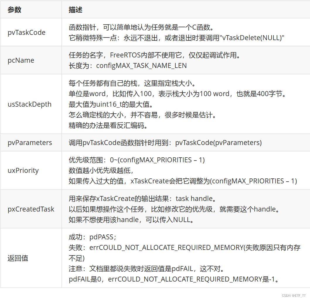
使用freeRTOS创建任务时使用如下函数

函数的参数
创建一个FreeRTOS任务点亮led灯实现led灯500毫秒翻转一次


具体的代码实现
#include "stm32f10x.h"                  // Device header
#include "Delay.h"
#include "freeRTOS.h"
#include "task.h"void Led_Init(void){RCC_APB2PeriphClockCmd(RCC_APB2Periph_GPIOA,ENABLE);   // 开启RCC外设时钟控制GPIO_InitTypeDef GPIO_InitStructure;                   // 结构体初始化GPIO_InitStructure.GPIO_Mode = GPIO_Mode_Out_PP;       // 使用推挽输出GPIO_InitStructure.GPIO_Pin = GPIO_Pin_0 | GPIO_Pin_1; // 开启GPIOA_Pin_1 引脚和GPIOA_Pin_0引脚GPIO_InitStructure.GPIO_Speed = GPIO_Speed_50MHz;      // 时钟的频率为50MHz GPIO_Init(GPIOA, &GPIO_InitStructure);                 // 初始化时钟的结构体           	  GPIO_ResetBits(GPIOA, GPIO_Pin_0 | GPIO_Pin_1);        // 设置引脚的默认电平为低电平
}void Led0_ON(void){GPIO_SetBits(GPIOA, GPIO_Pin_0);  // 引脚的电平为高电平
}void Led0_OFF(void){GPIO_ResetBits(GPIOA, GPIO_Pin_0); // 引脚的电平为低电平
}void Led1_ON(void){GPIO_SetBits(GPIOA, GPIO_Pin_1);
}void Led1_OFF(void){GPIO_ResetBits(GPIOA, GPIO_Pin_1);
}void LED_Turn0(void){ // led0电平翻转if(GPIO_ReadOutputDataBit(GPIOA, GPIO_Pin_0) == 0){GPIO_SetBits(GPIOA, GPIO_Pin_0);	}else{GPIO_ResetBits(GPIOA, GPIO_Pin_0);}}void LED_Turn1(void){  // led1电平翻转// 读取用输出寄存器中的某一位if(GPIO_ReadOutputDataBit(GPIOA, GPIO_Pin_1) == 0){GPIO_SetBits(GPIOA, GPIO_Pin_1);	}else{GPIO_ResetBits(GPIOA, GPIO_Pin_1);}}
// 创建FreeRTOS的句柄
TaskHandle_t Handle_task1;void Task1Function(void * pram){ while(1){LED_Turn0();vTaskDelay(500);Led0_OFF();vTaskDelay(500);	LED_Turn1();vTaskDelay(500);Led1_OFF();vTaskDelay(500);}
}int main(void){Led_Init();// 创建FreeRTOS的任务函数xTaskCreate(Task1Function,"task1",128,NULL,1,&Handle_task1);vTaskStartScheduler();while(1){}}
debug查看输出的pwm波形验证该测试时是成功的,开发板有反馈


注:基础知识部分参考学习自韦东山老师学习文档
串口实现程序创建并查看返回结果
void Task1Function(void * pram){while(1){printf("1");}
}
void Task2Function(void * pram){while(1){printf("2");}
}int main( void )
{TaskHandle_t xHandleTask1;#ifdef DEBUGdebug();
#endifprvSetupHardware();printf("Hello, world!\r\n");xTaskCreate(Task1Function,"Task1",100,NULL,1,&xHandleTask1);xTaskCreate(Task2Function,"Task2",100,NULL,1,NULL);vTaskStartScheduler();/* Will only get here if there was not enough heap space to create theidle task. */return 0;
}
代码只需要编写以上部分即可
#include <stdio.h>/* Scheduler includes. */
#include "FreeRTOS.h"
#include "task.h"
#include "queue.h"/* Library includes. */
#include "stm32f10x_it.h"/* Demo app includes. */
#include "lcd.h"
#include "LCD_Message.h"
#include "BlockQ.h"
#include "death.h"
#include "integer.h"
#include "blocktim.h"
#include "partest.h"
#include "semtest.h"
#include "PollQ.h"
#include "flash.h"
#include "comtest2.h"
#include "serial.h"/* Task priorities. */
#define mainQUEUE_POLL_PRIORITY				( tskIDLE_PRIORITY + 2 )
#define mainCHECK_TASK_PRIORITY				( tskIDLE_PRIORITY + 3 )
#define mainSEM_TEST_PRIORITY				( tskIDLE_PRIORITY + 1 )
#define mainBLOCK_Q_PRIORITY				( tskIDLE_PRIORITY + 2 )
#define mainCREATOR_TASK_PRIORITY           ( tskIDLE_PRIORITY + 3 )
#define mainFLASH_TASK_PRIORITY				( tskIDLE_PRIORITY + 1 )
#define mainCOM_TEST_PRIORITY				( tskIDLE_PRIORITY + 1 )
#define mainINTEGER_TASK_PRIORITY           ( tskIDLE_PRIORITY )/* Constants related to the LCD. */
#define mainMAX_LINE						( 240 )
#define mainROW_INCREMENT					( 24 )
#define mainMAX_COLUMN						( 20 )
#define mainCOLUMN_START					( 319 )
#define mainCOLUMN_INCREMENT 				( 16 )/* The maximum number of message that can be waiting for display at any one
time. */
#define mainLCD_QUEUE_SIZE					( 3 )/* The check task uses the sprintf function so requires a little more stack. */
#define mainCHECK_TASK_STACK_SIZE			( configMINIMAL_STACK_SIZE + 50 )/* Dimensions the buffer into which the jitter time is written. */
#define mainMAX_MSG_LEN						25/* The time between cycles of the 'check' task. */
#define mainCHECK_DELAY						( ( TickType_t ) 5000 / portTICK_PERIOD_MS )/* The number of nano seconds between each processor clock. */
#define mainNS_PER_CLOCK ( ( unsigned long ) ( ( 1.0 / ( double ) configCPU_CLOCK_HZ ) * 1000000000.0 ) )/* Baud rate used by the comtest tasks. */
#define mainCOM_TEST_BAUD_RATE		( 115200 )/* The LED used by the comtest tasks. See the comtest.c file for more
information. */
#define mainCOM_TEST_LED			( 3 )/*-----------------------------------------------------------*//** Configure the clocks, GPIO and other peripherals as required by the demo.*/
static void prvSetupHardware( void );/** Retargets the C library printf function to the USART.*/
int fputc( int ch, FILE *f );/** Configures the timers and interrupts for the fast interrupt test as* described at the top of this file.*/
extern void vSetupTimerTest( void );/*-----------------------------------------------------------*/void Task1Function(void * pram){while(1){printf("1");}
}
void Task2Function(void * pram){while(1){printf("2");}
}int main( void )
{TaskHandle_t xHandleTask1;#ifdef DEBUGdebug();
#endifprvSetupHardware();printf("Hello, world!\r\n");xTaskCreate(Task1Function,"Task1",100,NULL,1,&xHandleTask1);xTaskCreate(Task2Function,"Task2",100,NULL,1,NULL);vTaskStartScheduler();/* Will only get here if there was not enough heap space to create theidle task. */return 0;
}
/*-----------------------------------------------------------*//*-----------------------------------------------------------*//*-----------------------------------------------------------*/static void prvSetupHardware( void )
{/* Start with the clocks in their expected state. */RCC_DeInit();/* Enable HSE (high speed external clock). */RCC_HSEConfig( RCC_HSE_ON );/* Wait till HSE is ready. */while( RCC_GetFlagStatus( RCC_FLAG_HSERDY ) == RESET ){}/* 2 wait states required on the flash. */*( ( unsigned long * ) 0x40022000 ) = 0x02;/* HCLK = SYSCLK */RCC_HCLKConfig( RCC_SYSCLK_Div1 );/* PCLK2 = HCLK */RCC_PCLK2Config( RCC_HCLK_Div1 );/* PCLK1 = HCLK/2 */RCC_PCLK1Config( RCC_HCLK_Div2 );/* PLLCLK = 8MHz * 9 = 72 MHz. */RCC_PLLConfig( RCC_PLLSource_HSE_Div1, RCC_PLLMul_9 );/* Enable PLL. */RCC_PLLCmd( ENABLE );/* Wait till PLL is ready. */while(RCC_GetFlagStatus(RCC_FLAG_PLLRDY) == RESET){}/* Select PLL as system clock source. */RCC_SYSCLKConfig( RCC_SYSCLKSource_PLLCLK );/* Wait till PLL is used as system clock source. */while( RCC_GetSYSCLKSource() != 0x08 ){}/* Enable GPIOA, GPIOB, GPIOC, GPIOD, GPIOE and AFIO clocks */RCC_APB2PeriphClockCmd(	RCC_APB2Periph_GPIOA | RCC_APB2Periph_GPIOB |RCC_APB2Periph_GPIOC| RCC_APB2Periph_GPIOD | RCC_APB2Periph_GPIOE | RCC_APB2Periph_AFIO, ENABLE );/* SPI2 Periph clock enable */RCC_APB1PeriphClockCmd( RCC_APB1Periph_SPI2, ENABLE );/* Set the Vector Table base address at 0x08000000 */NVIC_SetVectorTable( NVIC_VectTab_FLASH, 0x0 );NVIC_PriorityGroupConfig( NVIC_PriorityGroup_4 );/* Configure HCLK clock as SysTick clock source. */SysTick_CLKSourceConfig( SysTick_CLKSource_HCLK );SerialPortInit();
}
/*-----------------------------------------------------------*//*-----------------------------------------------------------*//*-----------------------------------------------------------*/#ifdef  DEBUG
/* Keep the linker happy. */
void assert_failed( unsigned char* pcFile, unsigned long ulLine )
{for( ;; ){}
}
#endif
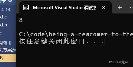
串口打印效果如下所示
RTOS的核心就是一个多任务系统,这个多任务系统好像是在多任务执行的,但是实际上是交叉执行的





![[lesson27]二阶构造模式](https://img-blog.csdnimg.cn/direct/86fc2ec52f854f98943b2124b5856818.png#pic_center)

![[通俗易懂:Linux标准输入/输出和重定向]Shell脚本之 > /dev/null 2>1命令详解](https://img-blog.csdnimg.cn/20201211150516784.png?x-oss-process=image/watermark,type_ZmFuZ3poZW5naGVpdGk,shadow_10,text_aHR0cHM6Ly9ibG9nLmNzZG4ubmV0L3FxXzQ0NDkxNzA5,size_16,color_FFFFFF,t_70)
