上一节完成了指定角度距离的测量这一节我们将其合成ROS的laserscan消息,并将其通过microros发布到上位机,最终实现rviz2的可视化。
一、雷达消息介绍
使用指令ros2 interface show sensor_msgs/msg/LaserScan,可以看到ROS2对雷达数据接口的定义。
# Single scan from a planar laser range-finder
#
# If you have another ranging device with different behavior (e.g. a sonar
# array), please find or create a different message, since applications
# will make fairly laser-specific assumptions about this datastd_msgs/Header header # timestamp in the header is the acquisition time ofbuiltin_interfaces/Time stampint32 secuint32 nanosecstring frame_id# the first ray in the scan.## in frame frame_id, angles are measured around# the positive Z axis (counterclockwise, if Z is up)# with zero angle being forward along the x axisfloat32 angle_min            # start angle of the scan [rad]
float32 angle_max            # end angle of the scan [rad]
float32 angle_increment      # angular distance between measurements [rad]float32 time_increment       # time between measurements [seconds] - if your scanner# is moving, this will be used in interpolating position# of 3d points
float32 scan_time            # time between scans [seconds]float32 range_min            # minimum range value [m]
float32 range_max            # maximum range value [m]float32[] ranges             # range data [m]# (Note: values < range_min or > range_max should be discarded)
float32[] intensities        # intensity data [device-specific units].  If your# device does not provide intensities, please leave# the array empty.
1.1 header部分
头部分,主要是设置雷达的frame_id和时间戳,在microros中可以这样赋值
pub_msg.header.frame_id = micro_ros_string_utilities_set(pub_msg.header.frame_id, "laser"); // 初始化消息内容
int64_t current_time = rmw_uros_epoch_millis();
pub_msg.header.stamp.sec = current_time * 1e-3;
pub_msg.header.stamp.nanosec = current_time - pub_msg.header.stamp.sec * 1000;
1.2 数据部分
angle_min 当前数据中最小的测量角度
angle_max 当前数据中最大的测量角度
angle_increment 我们默认就是一次1度,所以可以直接写
pub_msg.angle_increment = 1.0 / 180 * PI;
time_increment 每个数据之间递增的时间,可以直接使用扫描的总之间除点数
scan_time 扫描时间,开始扫描到结束扫描的时间
range_min 最小范围可以直接赋值 我们设置成0.05即5cm
range_max 最大范围,我们直接设置成5.0m
ranges 测量的距离值数组
intensities 测量的强度,这里我们直接忽略即可
二、代码编写
直接在上一节工程上修改,全部代码如下,一次我们发布10个点,并且启动了ESP32的双核,同时采取了时间同步,保证雷达数据的时间戳正常。
#include <Arduino.h>
#include <micro_ros_platformio.h>
#include <WiFi.h>
#include <rcl/rcl.h>
#include <rclc/rclc.h>
#include <rclc/executor.h>
#include <ESP32Servo.h>#include <sensor_msgs/msg/laser_scan.h>
#include <micro_ros_utilities/string_utilities.h>#define PCOUNT 10
#define Trig 27 // 设定SR04连接的Arduino引脚
#define Echo 21rclc_executor_t executor;
rclc_support_t support;
rcl_allocator_t allocator;
rcl_node_t node;rcl_publisher_t publisher;           // 声明话题发布者
sensor_msgs__msg__LaserScan pub_msg; // 声明消息文件

Servo servo1;
bool connected_agent = false;void microros_task(void *param)
{IPAddress agent_ip;                                                    // 设置通过WIFI进行MicroROS通信agent_ip.fromString("192.168.2.105");                                  // 从字符串获取IP地址set_microros_wifi_transports("fishbot", "12345678", agent_ip, 8888);   // 设置wifi名称,密码,电脑IP,端口号delay(2000);                                                           // 延时时一段时间,等待设置完成allocator = rcl_get_default_allocator();                               // 初始化内存分配器rclc_support_init(&support, 0, NULL, &allocator);                      // 创建初始化选项rclc_node_init_default(&node, "example20_simple_laser", "", &support); // 创建节点rclc_publisher_init_default(                                           // 发布初始化&publisher,&node,ROSIDL_GET_MSG_TYPE_SUPPORT(sensor_msgs, msg, LaserScan),"/scan");rclc_executor_init(&executor, &support.context, 1, &allocator);                             // 创建执行器pub_msg.header.frame_id = micro_ros_string_utilities_set(pub_msg.header.frame_id, "laser"); // 初始化消息内容pub_msg.angle_increment = 1.0 / 180 * PI;pub_msg.range_min = 0.05;pub_msg.range_max = 5.0;while (true){delay(10);if (!rmw_uros_epoch_synchronized()) // 判断时间是否同步
    {rmw_uros_sync_session(1000); //  同步时间continue;}connected_agent = true;rclc_executor_spin_some(&executor, RCL_MS_TO_NS(100)); // 循环处理数据
  }
}float get_distance(int angle)
{static double mtime;servo1.write(angle);     // 移动到指定角度delay(25);               // 稳定身形digitalWrite(Trig, LOW); // 测量距离delayMicroseconds(2);digitalWrite(Trig, HIGH);delayMicroseconds(10); // 产生一个10us的高脉冲去触发SR04
  digitalWrite(Trig, LOW);mtime = pulseIn(Echo, HIGH);                  // 检测脉冲宽度,注意返回值是微秒usfloat detect_distance = mtime / 58.0 / 100.0; // 计算出距离,输出的距离的单位是厘米cmSerial.printf("point(%d,%f)\n", angle, detect_distance);return detect_distance;
}void setup()
{Serial.begin(115200);pinMode(Trig, OUTPUT);     // 初始化舵机和超声波pinMode(Echo, INPUT);      // 要检测引脚上输入的脉冲宽度,需要先设置为输入状态servo1.setPeriodHertz(50); // Standard 50hz servoservo1.attach(4, 500, 2500);servo1.write(90.0);xTaskCreatePinnedToCore(microros_task, "microros_task", 10240, NULL, 1, NULL, 0);
}void loop()
{if (!connected_agent)return;static float ranges[PCOUNT + 1];for (int i = 0; i < int(180 / PCOUNT); i++){int64_t start_scan_time = rmw_uros_epoch_millis();for (int j = 0; j < PCOUNT; j++){int angle = i * 10 + j;ranges[j] = get_distance(angle);}pub_msg.angle_min = float(i * 10) / 180 * PI;       // 结束角度pub_msg.angle_max = float(i * (10 + 1)) / 180 * PI; // 结束角度
int64_t current_time = rmw_uros_epoch_millis();pub_msg.scan_time = float(current_time - start_scan_time) * 1e-3;pub_msg.time_increment = pub_msg.scan_time / PCOUNT;pub_msg.header.stamp.sec = current_time * 1e-3;pub_msg.header.stamp.nanosec = current_time - pub_msg.header.stamp.sec * 1000;pub_msg.ranges.data = ranges;pub_msg.ranges.capacity = PCOUNT;pub_msg.ranges.size = PCOUNT;rcl_publish(&publisher, &pub_msg, NULL);delay(10);}
}
三、下载测试
下载代码
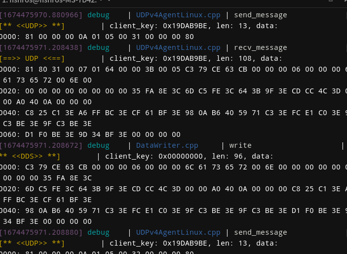
启动agent。
docker run -it --rm -v /dev:/dev -v /dev/shm:/dev/shm --privileged --net=host microros/micro-ros-agent:$ROS_DISTRO udp4 --port 8888 -v6
测试
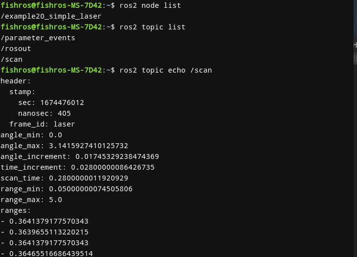
ros2 node list
ros2 topic list
ros2 topic echo /scan
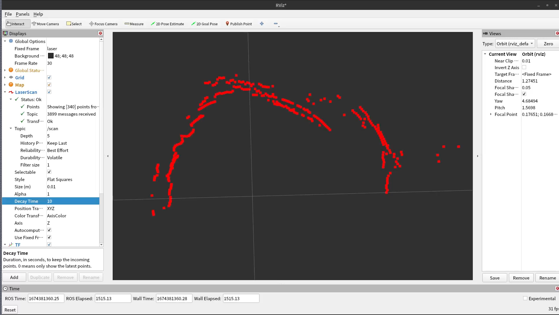
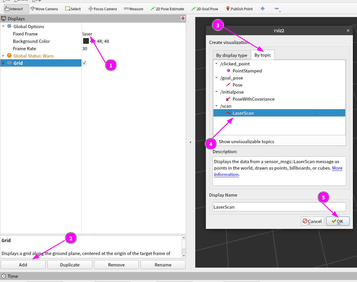
接着打开终端,输入rviz2打开rviz
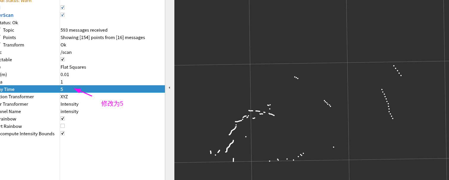
修改配置,显示过去5s数据
四、总结
本节我们成功实现了使用超声波和舵机模拟雷达数据,并将其合成scan发布到电脑上使用rviz2进行可视化。至此我们完成了ROS2硬件控制的所有课程。下面迎接你的将是移动机器人和机械臂开发课程,请做好准备,继续出发。
int64_t current_time = rmw_uros_epoch_millis();
pub_msg.header.stamp.sec = current_time * 1e-3;
pub_msg.header.stamp.nanosec = current_time - pub_msg.header.stamp.sec * 1000;