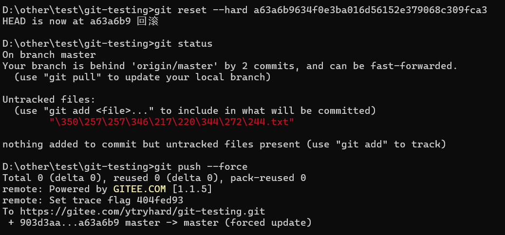
在上一篇博客中配置了UVW三相PWM的定时器,在此基础上增加配置ABZ编码器定时器
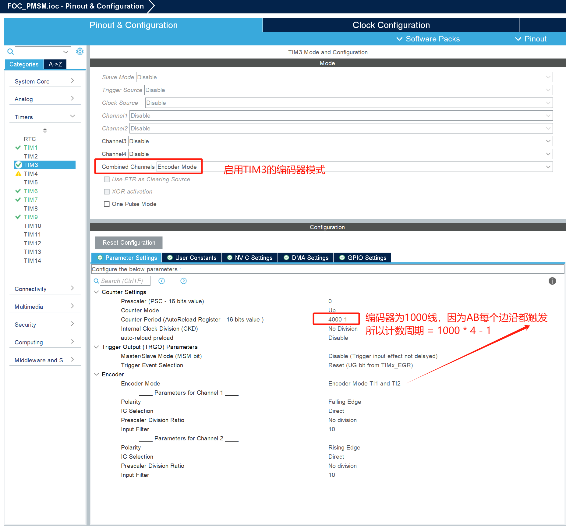
启用一个定时器中断,用于PID处理
代码如下

// 常量定义
#define PI 3.14159265359f
#define PWM_RESOLUTION 5250.0f  // PWM分辨率
#define CIRCLE_RESOLUTION 1000  // 圆周分辨率
#define MOTOR_PP  4             // 电机极对数
#define MAX_MOTORS 2            // 最大电机数量
#define MAX_ANGULAR_VELOCITY 2.0f  // 定义最大电角速度// 电机参数结构体
typedef struct {float voltage_power_supply;     // 电机电压float zero_electric_angle;      // 零电角位置float dc_a, dc_b, dc_c;         // 三相PWM占空比float Ualpha, Ubeta, Ua, Ub, Uc; // 坐标变换后的电压int32_t cur_pos;                // 当前编码器位置float rad_per_num;              // 每个脉冲对应的电角度变化uint8_t direction;              // 电机转向int32_t circle_count;           // 圆周计数// PI控制参数float prev_angle_error, integral_angle_error;  // 电角度PI控制误差float prev_angular_velocity_error, integral_angular_velocity_error;  // 电角速度PI控制误差float Kp_angular_velocity, Ki_angular_velocity; // 电角速度PI控制增益float outP_angular_velocity, outI_angular_velocity; // 电角速度PI控制输出// Uq控制PI参数float Kp_Uq, Ki_Uq;float max_Uq;               // Uq最大值// 目标角度和当前角度float set_angle, cur_angle, tar_angle;// PWM和编码器的定时器TIM_HandleTypeDef *pwm_timer;  // PWM输出定时器TIM_HandleTypeDef *enc_timer_ab; // 编码器A和B信号的定时器TIM_HandleTypeDef *enc_timer_z;  // 编码器Z信号的定时器
} Motor;// 全局电机实例数组
Motor motors[MAX_MOTORS];// 函数原型声明
void setPwm(Motor *motor, float Ua, float Ub, float Uc);
float getCurrentAngle(Motor *motor);
float wrapAngle(float angle, float period);
void moveToPosition(Motor *motor);
void initFocMotor(int motor_idx, TIM_HandleTypeDef *pwm_timer, TIM_HandleTypeDef *enc_timer_ab, TIM_HandleTypeDef *enc_timer_z);
void setPhaseVoltage(Motor *motor, float Uq, float Ud, float angle_el);// 约束函数:限制输入值在[min, max]范围内
float _constrain(float x, float min, float max) {return (x < min) ? min : (x > max) ? max : x;
}// 电角度归一化函数:将角度归一化到[0, 2PI]区间
float _normalizeAngle(float angle) {float a = fmod(angle, 2 * PI);  // 模运算return a >= 0 ? a : (a + 2 * PI);  // 如果角度为负,调整为正
}// 设置PWM输出函数:将电压转换为PWM占空比并输出
void setPwm(Motor *motor, float Ua, float Ub, float Uc) {// 根据电压计算PWM占空比,并约束在[0, 1]范围内motor->dc_a = _constrain(Ua / motor->voltage_power_supply, 0.0f, 1.0f);motor->dc_b = _constrain(Ub / motor->voltage_power_supply, 0.0f, 1.0f);motor->dc_c = _constrain(Uc / motor->voltage_power_supply, 0.0f, 1.0f);// 将PWM占空比转换为实际的PWM值uint32_t pwm_a = (uint32_t)(motor->dc_a * PWM_RESOLUTION);uint32_t pwm_b = (uint32_t)(motor->dc_b * PWM_RESOLUTION);uint32_t pwm_c = (uint32_t)(motor->dc_c * PWM_RESOLUTION);// 使用电机的PWM定时器设置PWM值__HAL_TIM_SET_COMPARE(motor->pwm_timer, TIM_CHANNEL_1, pwm_a);__HAL_TIM_SET_COMPARE(motor->pwm_timer, TIM_CHANNEL_2, pwm_b);__HAL_TIM_SET_COMPARE(motor->pwm_timer, TIM_CHANNEL_3, pwm_c);
}// 获取电机当前位置函数:根据编码器计数值计算电机位置
int32_t calculatePosition(Motor *motor) {int32_t count = __HAL_TIM_GET_COUNTER(motor->enc_timer_ab) / 4;int32_t position = count + (motor->circle_count * CIRCLE_RESOLUTION);return position;
}// 获取当前电角度:根据编码器计数值计算电角度
float getCurrentAngle(Motor *motor) {// 获取编码器A信号的计数值并计算电角度int32_t tim_count = __HAL_TIM_GET_COUNTER(motor->enc_timer_ab) / 4;return (float)(motor->rad_per_num * tim_count);  // 每个计数对应的电角度
}void moveToPosition(Motor *motor) {motor->cur_angle = getCurrentAngle(motor);  // 获取当前电角度float angle_error = motor->tar_angle - motor->cur_angle;  // 计算角度误差// 电角速度PI控制motor->outP_angular_velocity = motor->Kp_angular_velocity * angle_error;motor->outP_angular_velocity = _constrain(motor->outP_angular_velocity, -MAX_ANGULAR_VELOCITY, MAX_ANGULAR_VELOCITY);  // 限制PI输出
motor->outI_angular_velocity += motor->Ki_angular_velocity * angle_error;motor->outI_angular_velocity = _constrain(motor->outI_angular_velocity, -MAX_ANGULAR_VELOCITY, MAX_ANGULAR_VELOCITY);  // 限制PI积分输出// 计算期望电角速度,并限制在[-MAX_ANGULAR_VELOCITY, MAX_ANGULAR_VELOCITY]范围内float desired_angular_velocity = motor->outP_angular_velocity + motor->outI_angular_velocity;desired_angular_velocity = _constrain(desired_angular_velocity, -MAX_ANGULAR_VELOCITY, MAX_ANGULAR_VELOCITY);// 控制Uq(磁场方向电压)float Uq = motor->Kp_Uq * angle_error + motor->Ki_Uq * motor->integral_angle_error;Uq = _constrain(Uq, -motor->max_Uq, motor->max_Uq);  // 使用Uq最大值限制Uq = fabs(Uq);  // 保证Uq为正值
motor->set_angle = motor->cur_angle + desired_angular_velocity;  // 设定目标电角度setPhaseVoltage(motor, Uq, 0, motor->set_angle);  // 设置相电压
}// 设置相电压:根据Uq和电角度计算相电压并输出PWM信号
void setPhaseVoltage(Motor *motor, float Uq, float Ud, float angle_el) {angle_el = _normalizeAngle(angle_el + motor->zero_electric_angle);  // 归一化电角度// 逆Park变换motor->Ualpha = -Uq * sin(angle_el);motor->Ubeta = Uq * cos(angle_el);// 逆Clarke变换motor->Ua = motor->Ualpha + motor->voltage_power_supply / 2.0f;motor->Ub = (sqrt(3.0f) * motor->Ubeta - motor->Ualpha) / 2.0f + motor->voltage_power_supply / 2.0f;motor->Uc = (-motor->Ualpha - sqrt(3.0f) * motor->Ubeta) / 2.0f + motor->voltage_power_supply / 2.0f;// 设置PWM输出setPwm(motor, motor->Ua, motor->Ub, motor->Uc);
}// 初始化FOC控制:启动PWM定时器和编码器定时器
// 通过传入电机索引和定时器参数来指定初始化哪个电机,并配置相关定时器
void initFocMotor(int motor_idx, TIM_HandleTypeDef *pwm_timer, TIM_HandleTypeDef *enc_timer_ab, TIM_HandleTypeDef *enc_timer_z) {// 检查电机索引是否有效if (motor_idx >= MAX_MOTORS) {// 如果索引超出范围,返回错误
        Error_Handler();}// 初始化电机参数motors[motor_idx].max_Uq = 8;                 // 设置Uq最大值,改变此值可以改变速度,理论最大值为母线电压的一半,即24/2 = 12,但是实际设为12电机会卡住,具体设为多少根据电机以及负载而定motors[motor_idx].voltage_power_supply = 24.0f;    // 设置电机电压motors[motor_idx].zero_electric_angle = 0.0f;       // 设置零电角度motors[motor_idx].rad_per_num = MOTOR_PP * 2 * PI / CIRCLE_RESOLUTION * -1; // 每个脉冲对应的电角度变化// 设置PI控制器参数motors[motor_idx].Kp_angular_velocity = 1.0f;motors[motor_idx].Ki_angular_velocity = 0.01f;motors[motor_idx].Kp_Uq = 1.0f;motors[motor_idx].Ki_Uq = 0.0f;// 初始化定时器motors[motor_idx].pwm_timer = pwm_timer;motors[motor_idx].enc_timer_ab = enc_timer_ab;motors[motor_idx].enc_timer_z = enc_timer_z;// 启动PWM输出(主输出和互补输出)if (HAL_TIM_PWM_Start(motors[motor_idx].pwm_timer, TIM_CHANNEL_1) != HAL_OK)Error_Handler();if (HAL_TIMEx_PWMN_Start(motors[motor_idx].pwm_timer, TIM_CHANNEL_1) != HAL_OK)Error_Handler();if (HAL_TIM_PWM_Start(motors[motor_idx].pwm_timer, TIM_CHANNEL_2) != HAL_OK)Error_Handler();if (HAL_TIMEx_PWMN_Start(motors[motor_idx].pwm_timer, TIM_CHANNEL_2) != HAL_OK)Error_Handler();if (HAL_TIM_PWM_Start(motors[motor_idx].pwm_timer, TIM_CHANNEL_3) != HAL_OK)Error_Handler();if (HAL_TIMEx_PWMN_Start(motors[motor_idx].pwm_timer, TIM_CHANNEL_3) != HAL_OK)Error_Handler();// 启动编码器定时器AB(ENCA和ENCB)if (HAL_TIM_Encoder_Start(motors[motor_idx].enc_timer_ab, TIM_CHANNEL_ALL) != HAL_OK)Error_Handler();// 启动编码器定时器Z(ENCZ)if (HAL_TIM_IC_Start(motors[motor_idx].enc_timer_z, TIM_CHANNEL_2) != HAL_OK)Error_Handler();
}// 编码器中断回调函数
void HAL_TIM_IC_CaptureCallback(TIM_HandleTypeDef *htim) {// 获取电机1的编码器信息if (htim->Instance == motors[0].enc_timer_z->Instance && htim->Channel == HAL_TIM_ACTIVE_CHANNEL_2) {// 获取电机当前的方向motors[0].direction = (htim3.Instance->CR1 & TIM_CR1_DIR) ? 0 : 1;// 根据方向更新转向次数if (motors[0].direction) {motors[0].direction++;} else {motors[0].direction--;}// 这里可以选择是否需要清零计数器// __HAL_TIM_SET_COUNTER(&htim3, 0); // 重置ENCA和ENCB的计时器
    }
}// 定时器溢出回调函数
void HAL_TIM_PeriodElapsedCallback(TIM_HandleTypeDef *htim) {// 处理电机控制定时器溢出if (htim->Instance == TIM6) {  // 判断是否是TIM6中断,周期为1msmoveToPosition(&motors[0]);  // 调用电机控制函数
    }
}int main(void)
{// 初始化电机0的FOC控制,传入对应的定时器initFocMotor(0, &htim1, &htim3, &htim9);// 强制将电角度保持在0setPhaseVoltage(&motors[0], 1.0f, 0.0f, 0.0f);osDelay(100);// 重置编码器计数器__HAL_TIM_SET_COUNTER(motors[0].enc_timer_ab, 0);// 启动FOC控制的定时器HAL_TIM_Base_Start_IT(&htim6);motors[0].tar_angle = -2 * PI;//设置电机到-2pi的电角度位置,如果目标电角度值在0到-8pi之间,处于位置模式。小于-8pi(一个机械周期,电机极对数为4,电角度 = 4 * 2pi)电机就会一直旋转。while(1){}
}
