一、实验目的
1:学会设计用IP核和原理图的方式设计电路,完成涉及1位数据的2选1多路选择器。
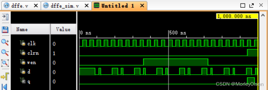
2:设计带异步置零和写使能端的D触发器。
二、实验环境
- 软件:Vivado 2015.4
- 操作系统:Windows 10
三、实验内容
2.2.1 多路选择器的设计
1:添加IP核文件
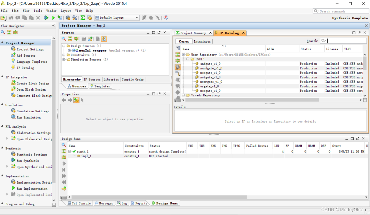
2:添加bd文件,在Block Design界面中进行设计

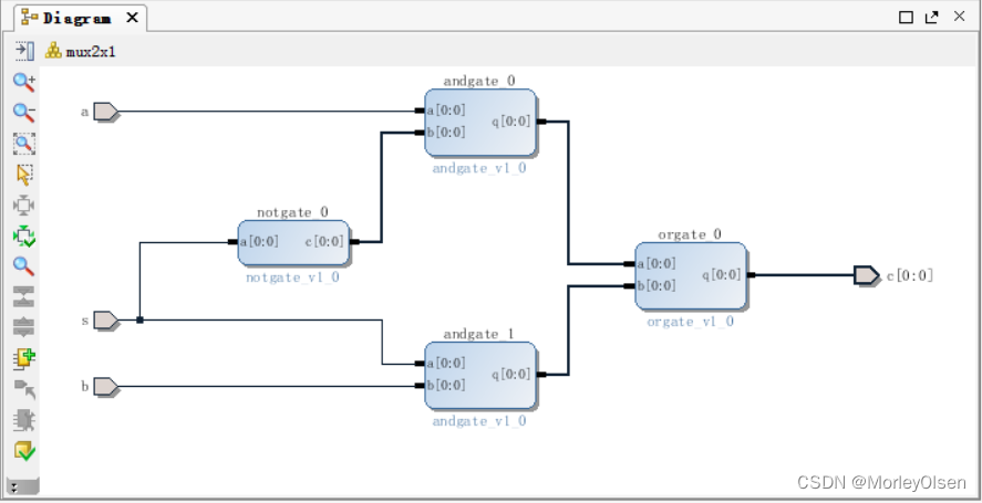
3:放置门电路及端口
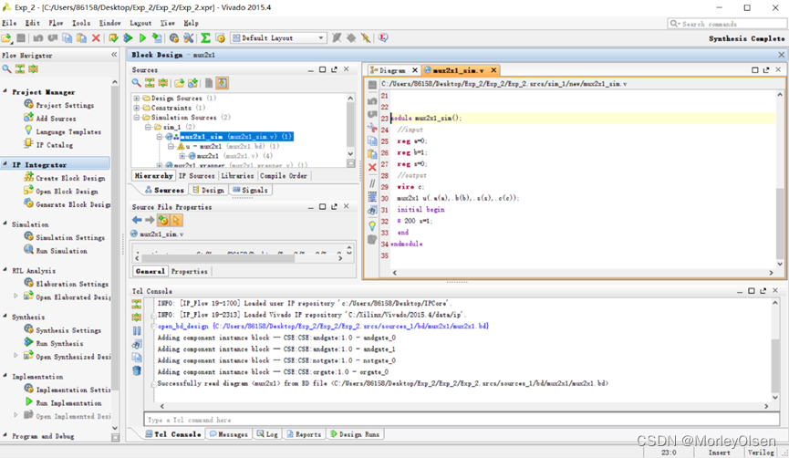
4:添加仿真文件并仿真
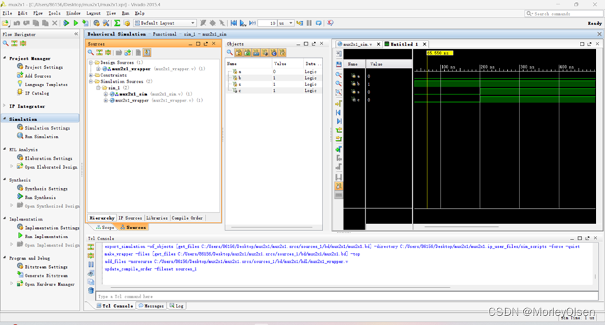
5:管脚分配
由于本实验不需要进行硬件实验,故2.2.1至此完毕

2.3.1 D触发器的设计
1:设置输入输出端口
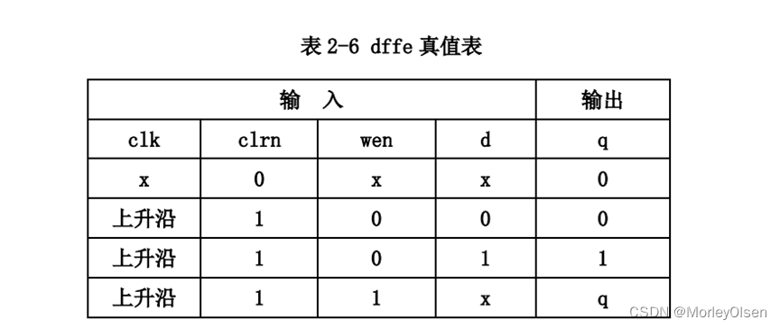
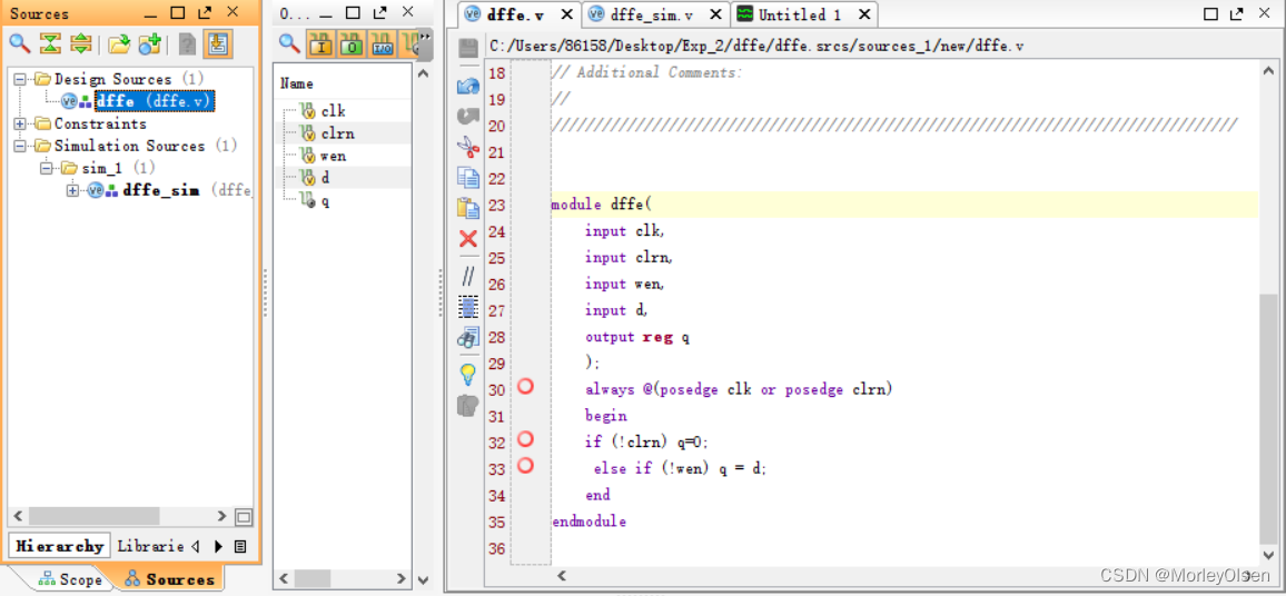
2:编写源程序文件
3:编写仿真程序文件
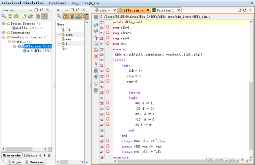
4 :仿真得到模拟图
四、分析Verilog 程序的功能,并编写仿真测试程序
源程序分析:
module reg8(
input clk, // 输入时钟信号input clrn, // 输入清除信号input wen, // 输入写使能信号input [7:0] d, // 输入数据信号output [7:0] q // 输出数据信号);reg [7:0] p; // 定义一个 8 位寄存器变量 palways @(posedge clk or negedge clrn) // 在时钟上升沿或清除信号下降沿时执行以下语句if(!clrn) // 如果清除信号为 0p <= 0; // 将寄存器清零else if (!wen) // 如果写使能信号为 0p <= d; // 将寄存器更新为输入数据信号assign q = p; // 将输出数据信号连接到寄存器变量 p 上
endmodule // 模块定义结束
仿真程序:
module reg8_sim;// Inputsreg clk;reg clrn;reg wen;reg [7:0] d;// Outputswire [7:0] q;// Instantiate the module to be testedreg8 dut (.clk(clk),.clrn(clrn),.wen(wen),.d(d),.q(q));// Clock generatoralways #5 clk = ~clk;// Testbench logicinitial begin// Initialize inputsclk = 0;clrn = 1;wen = 0;d = 0;// Wait for a few clock cycles#10;// Reset the moduleclrn = 0;#5 clrn = 1;// Wait for another few clock cycles#10;// Write some data to the modulewen = 1;d = 8'hAB;#5 wen = 0;// Wait for a few more clock cycles#10;// Read the data from the modulewen = 0;#5;$display("q = %h", q);// Finish the simulation#10;$finish;end
endmodule
仿真结果:

五、总结实验中遇到问题和解决方法
遇到的问题:
1:mux2x1verilog源文件在实验指导中存在一定问题,在仿真时c的输出为Z,即无输出。
解决的办法:
1:将源文件修改如下
| module mux2x1verilog( input a, input b, input s, output c ); wire a1,b1,sel; notgate_0 u0(.a(s),.c(sel)); andgate_0 u1(.a(a),.b(sel),.q(a1)); andgate_0 u2(.a(s),.b(b),.q(b1)); orgate_0 u3(.a(a1),.b(b1),.q(c)); endmodule |
由于实验指导里面未写入与门和或门的逻辑,因此无法正确运行程序。错误的仿真结果如下图:
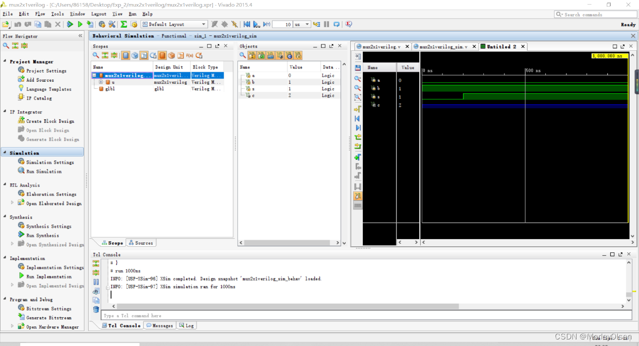
根据代码语义分析后,可以得到a1为与门1的输出、b1为与门2的输出,sel为非门的输出。根据电路图重写语句后,仿真结果符合预期。
其他说明:
Exp_2文件夹中,Exp_2、mux2x1verilog为2.2.1的实验内容,dffe为2.3.1的实验内容,reg8为第四部分的实验内容。



![[chatgpt+Azure]unity AI二次元小女友之使用微软Azure服务实现RestfulApi->语音识别+语音合成](https://img-blog.csdnimg.cn/img_convert/cf59bffe4cdf304c6a0534b651431e46.png)
