LTspice(14) Noise仿真
好久没有更新LTspice的教程了,大家想了没?
截止目前LTspice已经更新到24.0.9。界面发生了一些变化,但主要功能并不受影响,新的版本改了UI,找东西更加方便了,界面如下图1所示。

图1:LTspice新版本界面
这一讲我们仿真噪声,这一版本的LTspice的help使用了网页的形式展现,这样更加便于翻译软件的大展身手。
翻译后的Noise说明如下:
| This is a frequency domain analysis that computes the noise due to Johnson, shot and flicker noise. The output data is noise spectral density per unit square root bandwidth. Syntax: .noise V(<out>[,<ref>]) <src> <oct, dec, lin> <Nsteps> <StartFreq> <EndFreq> V(<out>[,<ref>]) is the node at which the total output noise is calculated. It can be expressed as V(n1, n2) to represent the voltage between two nodes. <src> is the name of an independent source to which input noise is referred. <src> is the noiseless input signal. The parameters <oct, dec, lin>, <Nsteps>, <StartFreq>, and <EndFreq> define the frequency range of interest and resolution in the manner used in the .ac directive. Output data trace V(onoise) is the noise spectral voltage density referenced to the node(s) specified as the output in the above syntax. If the input signal is given as a voltage source, then data trace V(inoise) is the input-referred noise voltage density. If the input is specified as a current source, then the data trace inoise is the noise referred to the input current source signal. The noise contribution of each component can be plotted. These contributions are referenced to the output. You can reference them to the input by dividing by the data trace "gain". The waveform viewer can integrate noise over a bandwidth by <Ctrl-Key> + left mouse button clicking on the corresponding data trace label. The syntax ".noise V(<out>[,<ref>]) <src> list <Freq>" with a single analysis frequency is useful in combination with .step. It allows you to plot noise densities as a function of a stepped parameter. |
新的help界面如下图2所示:
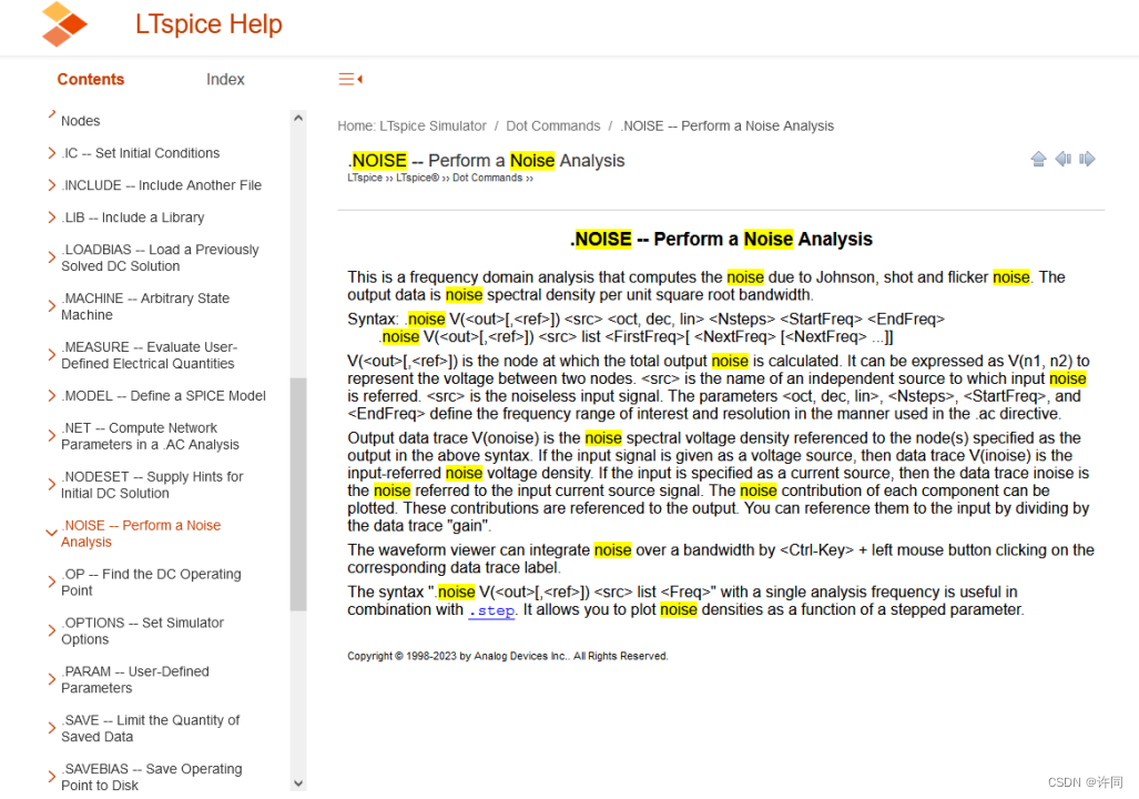
图2:LTspice新的帮助文件界面
好了,直接开始正题,构建一个简单的运算放大器跟随电路如下图3所示。注意LTspice中的OP07是ADI家的OP07,不能用LTspice的结果去带入其他家的OP07。
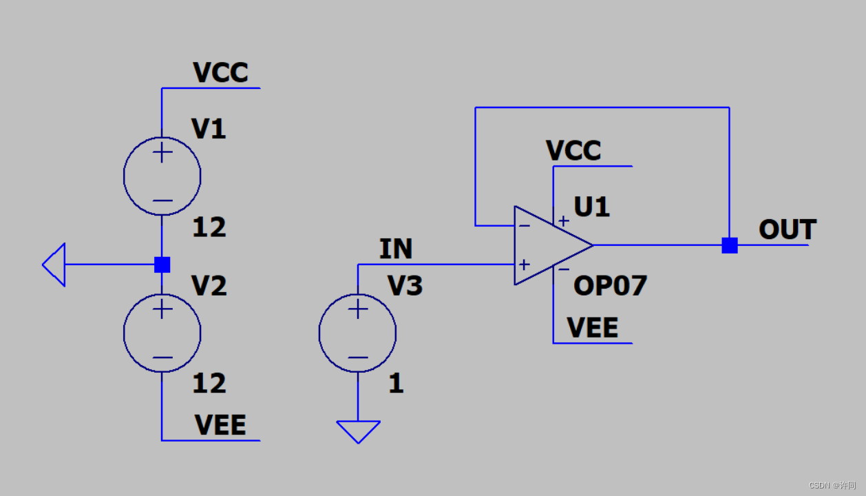
图3:基本跟随器电路
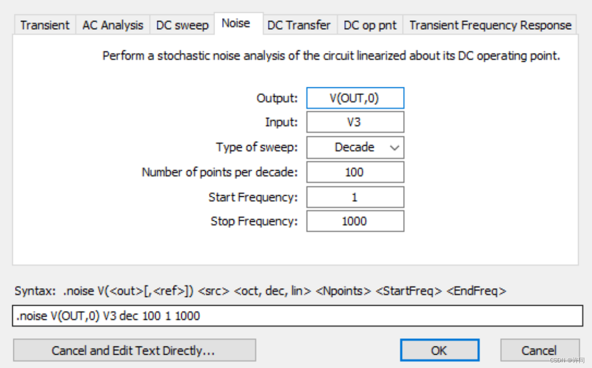
图4:仿真设置
图4中提供了仿真设置,OUT代表你要分析的最终信号ta需要两个网络节点,如果是参考GND的话,那就直接一个写网络标,另外一个写0,在Spice中0就是接地。Input代表你这个噪声相对是那个电压源的,直接写你输入的这个电压源就可以,在这里我们用的是V3电压源就直接设置为V3电压源即可,Type of sweep 设置扫描类型可以对数扫描10倍频程还是8倍频程,也可以线性扫描等等,然后选择扫描每10倍频程的点数,点数越多越精细。看ADI手册ADC的噪声扫描的范围是1Hz到1KHz那我们扫描也扫描1Hz到1KHz。详情如下图5所示。
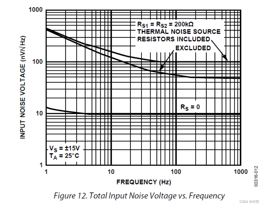
图5:ADI OP07 Noise
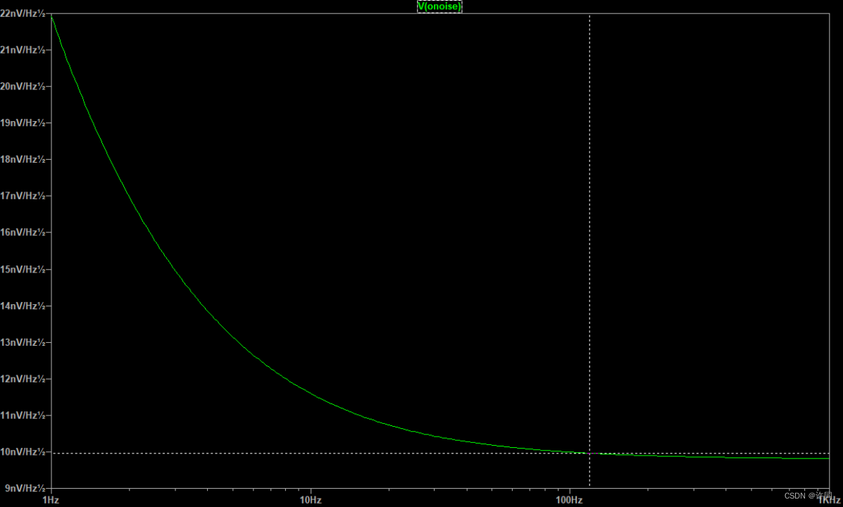
图6:ADI OP07仿真结果
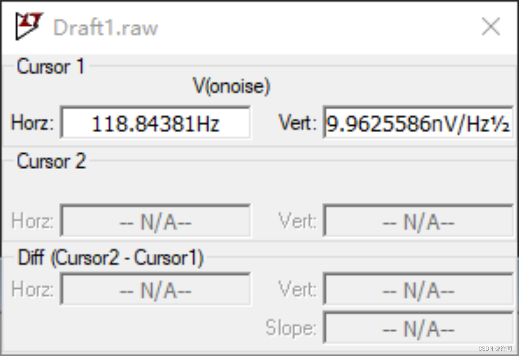
图7:ADI OP07仿真结果
从图6,图7的结果可以看出,仿真结果基本上和ADI OP07的手册相对应。仿真代码如仿真代码1所示。
仿真代码1:
| V1 VCC 0 12 V2 0 VEE 12 V3 IN 0 1 XU1 IN OUT VCC VEE OUT LT1001 .noise V(OUT,0) V3 dec 100 1 1000 .lib LTC.lib .backanno .end |
在试试看加强滤波输出啥效果,如图8所示,加了强滤波在118Hz左右时候Noise就1nV都不到了。
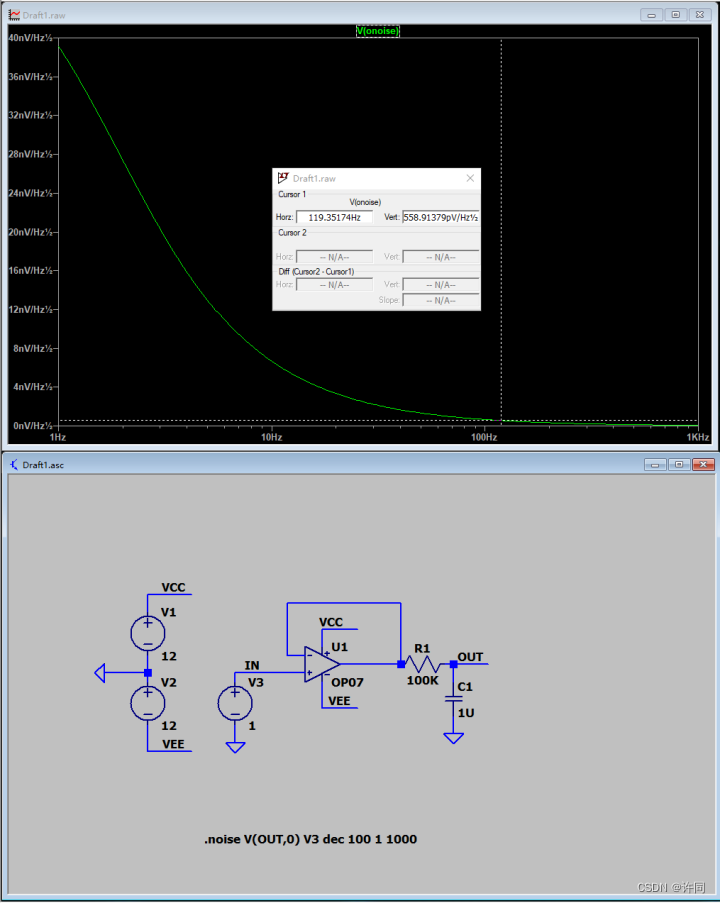
图8:加强滤波后的噪声输出效果
今天就先到这里了,关注xuyuntong 了解更多

一些信息:
翻译软件欧路词典

![基于51单片机的定时器时钟设计[proteus仿真]](https://img-blog.csdnimg.cn/direct/60d7f9d236c7413ab0e32ce0e2eddae8.png)
![[C/C++]string类常用接口介绍及模拟实现string类](https://img-blog.csdnimg.cn/direct/367e962274e24e46ba2abeee0f0bf148.png)
