实验题目如下:

实验拓扑如下:

实验要求如下:
【1】R6为ISP只能配置ip地址,R1-5的环回为私有网段
【2】R1/4/5为全连的MGRE结构,R1/2/3为星型的拓扑结构,R1为中心站点
【3】所有私有网段可以互相通讯,私有网段使用OSPF协议完成
实验思路如下:
(1)合理的IP配置
(2)公网全网可达,需要做到在R1~R5写静态缺省指向ISP
(3)要求二:R1/4/5为全连的MGRE结构
解释如下:
此处的三个IP都需要为固定IP
(4)要求二:R1/2/3为星型的拓扑结构
对于星型拓扑结构的解释:
只需要一个固定的公有IP作为中心站点,其余可以使用不固定的公有IP作为分支
(5)当使用OSPF协议完成私有网段后,需要划分到同一区域进行宣告身边的私有网段
实验步骤如下:
1、实现公网的全网可达(书写缺省路由)
指令如下:
R1:
ip route-static 0.0.0.0 0.0.0.0 16.1.1.2
ip route-static 0.0.0.0 0.0.0.0 61.1.1.2
R2:
ip route-static 0.0.0.0 0.0.0.0 26.1.1.2R3:
ip route-static 0.0.0.0 0.0.0.0 36.1.1.2R4:
ip route-static 0.0.0.0 0.0.0.0 46.1.1.2R5:
ip route-static 0.0.0.0 0.0.0.0 56.1.1.22、要求二:R1/4/5为全连MGRE结构
指令如下:
R1:
[R1]interface Tunnel 0/0/0
[R1-Tunnel0/0/0]ip add 192.168.6.1 24
[R1-Tunnel0/0/0]tunnel-protocol gre p2mp
[R1-Tunnel0/0/0]source 16.1.1.1
[R1-Tunnel0/0/0]nhrp entry 192.168.6.4 46.1.1.1 register
[R1-Tunnel0/0/0]nhrp entry 192.168.6.5 56.1.1.1 register
[R1-Tunnel0/0/0]nhrp network-id 100
R4:
[R4]interface Tunnel 0/0/0
[R4-Tunnel0/0/0]ip add 192.168.6.4 24
[R4-Tunnel0/0/0]tunnel-protocol gre p2mp
[R4-Tunnel0/0/0]source 46.1.1.1
[R4-Tunnel0/0/0]nhrp entry 192.168.6.1 16.1.1.1 register
[R4-Tunnel0/0/0]nhrp entry 192.168.6.5 56.1.1.1 register
[R4-Tunnel0/0/0]nhrp network-id 100
R5:
[R5]interface Tunnel 0/0/0
[R5-Tunnel0/0/0]ip add 192.168.6.5 24
[R5-Tunnel0/0/0]tunnel-protocol gre p2mp
[R5-Tunnel0/0/0]source 56.1.1.1
[R5-Tunnel0/0/0]nhrp entry 192.168.6.1 16.1.1.1 register
[R5-Tunnel0/0/0]nhrp entry 192.168.6.4 46.1.1.1 register
[R5-Tunnel0/0/0]nhrp network-id 100
3、要求二:R1/2/3为星型拓扑结构
指令如下:
R1:
[R1]interface Tunnel 0/0/1
[R1-Tunnel0/0/1]ip add 192.168.7.1 24
[R1-Tunnel0/0/1]tunnel-protocol gre p2mp
[R1-Tunnel0/0/1]source 61.1.1.1
[R1-Tunnel0/0/1]nhrp entry multicast dynamic
[R1-Tunnel0/0/1]nhrp network-id 10
R2:
[R2]interface Tunnel 0/0/1
[R2-Tunnel0/0/1]ip add 192.168.7.2 24
[R2-Tunnel0/0/1]tunnel-protocol gre p2mp
[R2-Tunnel0/0/1]source GigabitEthernet 0/0/0
[R2-Tunnel0/0/1]nhrp entry 192.168.7.1 61.1.1.1 register
[R2-Tunnel0/0/1]nhrp network-id 10
R3:
[R3]interface Tunnel 0/0/1
[R3-Tunnel0/0/1]ip add 192.168.7.3 24
[R3-Tunnel0/0/1]tunnel-protocol gre p2mp
[R3-Tunnel0/0/1]source GigabitEthernet 0/0/0
[R3-Tunnel0/0/1]nhrp entry 192.168.7.1 61.1.1.1 register
[R3-Tunnel0/0/1]nhrp network-id 10
4、使用OSPF协议完成私有网段
指令如下:
R1:
[R1]ospf 1 router-id 1.1.1.1
[R1-ospf-1]ar
[R1-ospf-1]area 0
[R1-ospf-1-area-0.0.0.0]network 192.168.1.0 0.0.0.255
[R1-ospf-1-area-0.0.0.0]network 192.168.6.0 0.0.0.255
[R1-ospf-1-area-0.0.0.0]network 192.168.7.0 0.0.0.255
R2:
[R2]ospf 1 router-id 2.2.2.2
[R2-ospf-1]area 0
[R2-ospf-1-area-0.0.0.0]network 192.168.2.0 0.0.0.255
[R2-ospf-1-area-0.0.0.0]network 192.168.7.0 0.0.0.255
R3:
[R3]ospf 1 router-id 3.3.3.3
[R3-ospf-1]area 0
[R3-ospf-1-area-0.0.0.0]network 192.168.3.0 0.0.0.255
[R3-ospf-1-area-0.0.0.0]network 192.168.7.0 0.0.0.255
R4:
[R4]ospf 1 router-id 4.4.4.4
[R4-ospf-1]area 0
[R4-ospf-1-area-0.0.0.0]ne
[R4-ospf-1-area-0.0.0.0]network 192.168.4.0 0.0.0.255
[R4-ospf-1-area-0.0.0.0]network 192.168.6.0 0.0.0.255
R5:
[R5]ospf 1 router-id 5.5.5.5
[R5-ospf-1]area 0
[R5-ospf-1-area-0.0.0.0]ne
[R5-ospf-1-area-0.0.0.0]network 192.168.5.0 0.0.0.255
[R5-ospf-1-area-0.0.0.0]network 192.168.6.0 0.0.0.255
5、让R2和R3退出选举(修改接口)
指令如下:
R1:
[R1]interface Tunnel 0/0/0
[R1-Tunnel0/0/0]ospf network-type broadcast
[R1]interface Tunnel 0/0/1
[R1-Tunnel0/0/1]ospf network-type broadcast
R2:
[R2]interface Tunnel 0/0/1
[R2-Tunnel0/0/1]ospf network-type broadcast
[R2-Tunnel0/0/1]ospf dr-priority 0
R3:
[R3]int Tunnel 0/0/1
[R3-Tunnel0/0/1]ospf network-type broadcast
[R3-Tunnel0/0/1]ospf dr-priority 0
R4:
[R4]int Tunnel 0/0/0
[R4-Tunnel0/0/0]ospf network-type broadcast
R5:
[R5]int Tunnel 0/0/0
[R5-Tunnel0/0/0]ospf network-type broadcast
测试如下:
IP配置:

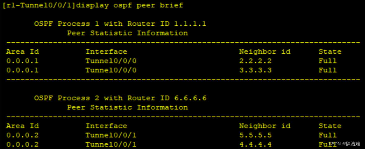
路由配置完成:


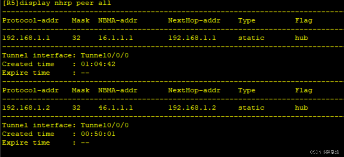
全网的网状结构:


