一些定义
PCIE复位:一些PCIE复位的知识链接
PCIE初始化:初始化相关定义看下面链接和下图
C语言简化初始化看本人的《DW PCIE的PCIE的RC和EP最简初始化学习笔记》文章。
Sticky Registers:与传统的复位方式相同,FLR方式不能复位这些寄存器,但是系统软件对部分Sticky Registers进行修改。当Vaux(备用电源)被移除后,这些寄存器中的保存的数据才会丢失。可以看前面PCIE复位详解部分内容。
ARI:Alternative Routing-ID Interpretation,顾名思义,可替换的Routing ID,意味着这是一种要把Routing ID的部分或全部替换掉的机制。使用ARI格式时,一个PCIe设备最多可以支持256个Function,而传统的PCIe设备最多只能支持8个Function。
ARI的介绍
Secondary Bus Number: 桥设备(Bridge)下游端口连接的 PCIe 总线号。
Subordinate Bus Number:挂载到桥设备(Bridge)下的最大的 PCIe 总线号。
Secondary Bus和Subordinate Bus Number介绍链接
BUS DEV FUNC的定义看下图和前面PCIE初始化的链接:
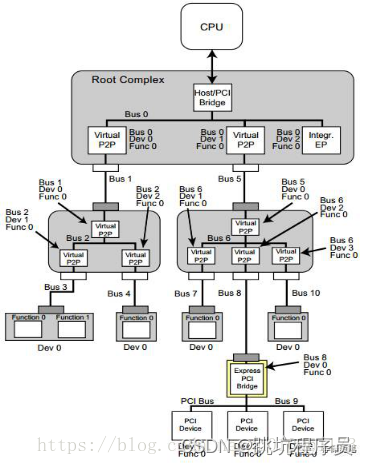
DW LINUX作为RC的底层操作调用
DBI寄存器和DBI2寄存器对应关系看文章DW PCIE 的Register Module, LBC, and DBI章节学习笔记
_pcie_write_dbi(0x710,0x70120);_pcie_write_dbi(0x80c,0x10430);_pcie_write_dbi(0x82c,0xffffffff);_pcie_write_dbi(0x828,0xffffffff);_pcie_read_dbi(0x8bc);_pcie_write_dbi(0x8bc,0xbff41);_pcie_write_dbi(0x100010,0);_pcie_write_dbi(0x10,0);_pcie_read_dbi(0x8bc);_pcie_write_dbi(0x8bc,0xbff40);_pcie_read_dbi(0x8bc);_pcie_write_dbi(0x8bc,0xbff41);_pcie_write_dbi(0x14,0);_pcie_read_dbi(0x8bc);_pcie_write_dbi(0x8bc,0xbff40);_pcie_read_dbi(0x8bc);_pcie_write_dbi(0x8bc,0xbff41);_pcie_read_dbi(0x3c);_pcie_write_dbi(0x3c,0x1ff);_pcie_read_dbi(0x8bc);_pcie_write_dbi(0x8bc,0xbff40);_pcie_read_dbi(0x18);_pcie_write_dbi(0x18,0xff0100);_pcie_read_dbi(0x4);_pcie_write_dbi(0x4,0x100107);_pcie_read_dbi(0x900);_pcie_write_dbi(0x300008,0xf9020000);_pcie_write_dbi(0x30000c,0);_pcie_write_dbi(0x300010,0xf9ffffff);_pcie_write_dbi(0x300014,0xf9020000);_pcie_write_dbi(0x300018,0x0);_pcie_write_dbi(0x300000,0x0);_pcie_write_dbi(0x300004,0x80000000);_pcie_read_dbi(0x300004);_pcie_write_dbi(0x300408,0xf9010000);_pcie_write_dbi(0x30040c,0);_pcie_write_dbi(0x300410,0xf901ffff);_pcie_write_dbi(0x300414,0xf9010000);_pcie_write_dbi(0x300418,0);_pcie_write_dbi(0x300400,0x2);_pcie_write_dbi(0x300404,0x80000000);_pcie_read_dbi(0x300404);_pcie_write_dbi(0x10,0);_pcie_read_dbi(0x8bc);_pcie_write_dbi(0x8bc,0xbff41);_pcie_write_dbi_16(0xa,0x604);_pcie_read_dbi(0x8bc);_pcie_write_dbi(0x8bc,0xbff40);_pcie_read_dbi(0x80c);_pcie_write_dbi(0x80c,0x30430);ATU
TLP 是什么看《DW PCIE 的TLP Processing章节学习笔记》
地址转换用于将不同的地址范围映射到支持的不同内存空间你的申请。 一个典型的示例将您的应用程序内存空间映射到 PCI 内存空间。 iATU还支持类型转换。 如果没有地址转换,您的应用程序地址会未经修改地传递直接通过 Tx 应用程序接口发送到 TLP。 您可以对 iATU 进行编程以实现您的自己的出站地址转换方案,无需外部逻辑。
ATU 简单理解就是一个Inband输入和Outband输出的地址转换,内部总线和PCIE总线产生一个对应关系的表。输入输出(非BAR匹配输入)关系实例图如下:
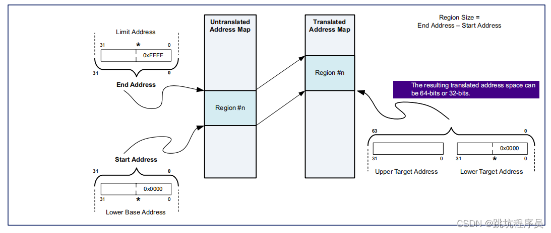
ATU寄存器说明
在文档中下面两个图放德顺序是掉过来的,开始我还理解不了什么意思。感觉调过来说比较好理解。
ATU寄存器地址说明,其中0-16位是有效地址位。16-9位是选择第几个ATU的范n围设置,8位是选择配置out输入还是输出的范围控制。(对于ATU有BYPASS模式,对应设置比如DMA输出可以不经过ATU转换)。我使用芯片0区域outbound读地址设置为0x300000地址开始,1区域读对应0x300200,Intbound写0区域地址应该为0x300100,1区域地址应该为0x300300。
LINUX下有这样的定义:
#define PCIE_DMA_UNR_CONTROL1_WRCH(ch)		(0x200 + ch * 0x200)
#define PCIE_DMA_UNR_TRANSFER_SIZE_WRCH(ch)	(0x208 + ch * 0x200)
#define PCIE_DMA_UNR_SAR_LOW_WRCH(ch)		(0x20c + ch * 0x200)
#define PCIE_DMA_UNR_SAR_HIGH_WRCH(ch)		(0x210 + ch * 0x200)
#define PCIE_DMA_UNR_DAR_LOW_WRCH(ch)		(0x214 + ch * 0x200)
#define PCIE_DMA_UNR_DAR_HIGH_WRCH(ch)		(0x218 + ch * 0x200)#define PCIE_DMA_UNR_CONTROL1_RDCH(ch)		(0x300 + ch * 0x200)
#define PCIE_DMA_UNR_TRANSFER_SIZE_RDCH(ch)	(0x308 + ch * 0x200)
#define PCIE_DMA_UNR_SAR_LOW_RDCH(ch)		(0x30c + ch * 0x200)
#define PCIE_DMA_UNR_SAR_HIGH_RDCH(ch)		(0x310 + ch * 0x200)
#define PCIE_DMA_UNR_DAR_LOW_RDCH(ch)		(0x314 + ch * 0x200)
#define PCIE_DMA_UNR_DAR_HIGH_RDCH(ch)		(0x318 + ch * 0x200)

ATU寄存器0-7位的选择:
Inband和Outband类似所以不特别说明。
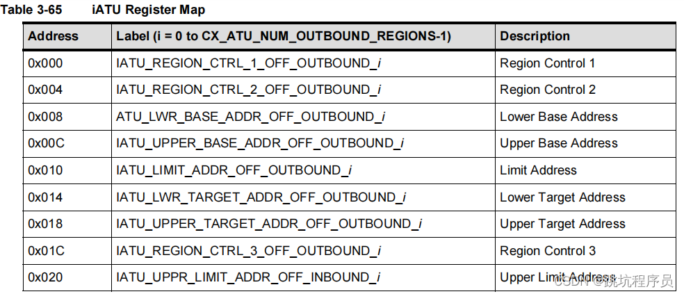
Region Control定义
在DATABOOK文档中没有找到Region Control的对应为的定义,在寄存器文档中有介绍,从LINUX 代码中找到了实际应用对应内容的定义,需要详细了解可以去看寄存器介绍文档。
控制寄存器1:
#define PCIE_ATU_TYPE_MEM (0x0 << 0)
#define PCIE_ATU_TYPE_IO (0x2 << 0)
#define PCIE_ATU_TYPE_CFG0 (0x4 << 0)
#define PCIE_ATU_TYPE_CFG1 (0x5 << 0)
控制寄存器2:
#define PCIE_ATU_ENABLE (0x1 << 31)
#define PCIE_ATU_BAR_MODE_ENABLE (0x1 << 30)
Outbound
Address translation is used for mapping different address ranges to different memory spaces supported by your application. A typical example maps your application memory space to PCI memory space. The iATU also supports type translation. Without address translation, your application address is passed unmodified to the TLPs directly through the Tx application interface. You can program the iATU to implement your own outbound address translation scheme without external logic.
地址转换用于将不同的地址范围映射到应用程序支持的不同内存空间。 一个典型的示例将您的应用程序内存空间映射到 PCI 内存空间。 iATU 还支持类型转换。 如果没有地址转换,您的应用程序地址会直接通过 Tx 应用程序接口未经修改地传递给 TLP。 您可以对 iATU 进行编程以实现您自己的出站地址转换方案,而无需外部逻辑。
Outbound Features:
■ Address Match mode operation for MEM and I/O, CFG, and MSG TLPs. No translation for completions.
MEM 和I/O、CFG 和MSG TLP 的地址匹配模式操作。没有传输完成包
■ Supports type translation through TLP type header field replacement for MEM or I/O types to MSG/CFG types.
通过将 MEM 或 I/O 类型的 TLP 类型标头字段替换为 MSG/CFG 类型,支持类型转换。
■ Programmable TLP header field replacement.
可编程TLP 报头字段替换
■ Multiple (up to 256) address regions programmable for location and size.
多个区域可配置
■ Programmable enable/disable per region.
可独立使能或禁止每个区域
■ Automatic FMT field translation between three DWORDs and four DWORDs for 64-bit addresses.
用于 64 位地址的三个 DWORD 和四个 DWORD 之间的自动 FMT 字段转换。
■ Invert Address Matching mode to translate accesses outside of a successful address match.
反转地址匹配模式以转换成功地址匹配之外的访问。
■ Configuration Shift mode. Optimizes the memory footprint of CFG accesses destined for the Rx application interface in a multifunction device.
配置转换模式。优化针对多功能设备中 Rx 应用程序接口的 CFG 访问的内存占用。
■ Response code which defines the completion status to return for accesses matching a region.
响应代码,它定义为匹配区域的访问返回的完成状态。
■ Payload Inhibit marks all TLPs as having no payload data.
Payload Inhibit 将所有 TLP 标记为没有有效负载数据。
■ Header Substitution replaces bytes 8 to 11 (for 3 DWORD header) or bytes 12 to 15 (for 4 DWORD header), inclusive, of the outbound TLP header.
标头替换替换字节 8 到 11(对于 3 DWORD 标头)或字节 12 到 15(对于 4 DWORDheader),包括出站 TLP 标头。
■ Tag Substitution of the outbound TLP tag field.
出站TLP 标记字段的标记替换
■ Function number bypass mode to allow function number information to be supplied from your application transmit interface while translating the address and other attributes of the TLP.
功能编号旁路模式允许从您的应用程序传输接口提供功能编号信息,同时转换 TLP 的地址和其他属性。
■ DMA bypass mode to allow TLPs which are initiated by the embedded DMA engine, to pass through the iATU untranslated.
DMA 旁路模式允许由嵌入式 DMA 引擎启动的 TLP 未经翻译地通过 iATU。
■ TLP Header fields bypass mode to allow header information to be supplied from your application transmit interface or, if AMBA is configured, from the AMBA sideband bus while translating the address and Type of the TLP.
TLP 报头字段绕过模式,允许从应用程序传输接口提供报头信息,或者,如果配置了 AMBA,则在转换 TLP 的地址和类型时,从 AMBA 边带总线提供报头信息。
Inbound
When there is no match, then the address is untranslated. In addition,
■除了输入不匹配不传输外Inbound还有2个限制
❑ TLPs destined for the internal CDM or ELBI in an upstream port are not translated.
不能传世CMD和ELBI的控制
❑ TLPs that are not error-free (ECRC, malformed, and so on) are not translated.ECRC:Generation and Checking
TLPS没有malformed和ECRC完成的将不能传输
■ Address translation of completions is not supported in Address Match mode.
地址转换结束(结束包?时路由的东西》)在地址匹配模式不支持。

在描述TLP Type内容中MEM I/O符合模式下有个有个BAR Match Mode需要注意,这个部分输入的范围是BAR确定的不是ATU设置的最低最高地址决定。
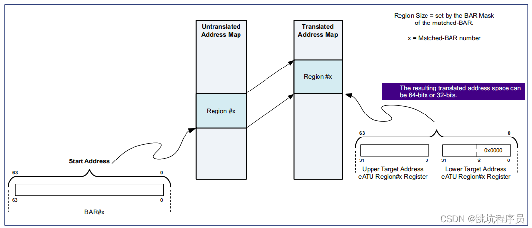
ATU中的 CFG_SHIFT_MODE和ECAM
下面介绍的原链接
PCI Express Enhanced Configuration Access Mechanism (ECAM)
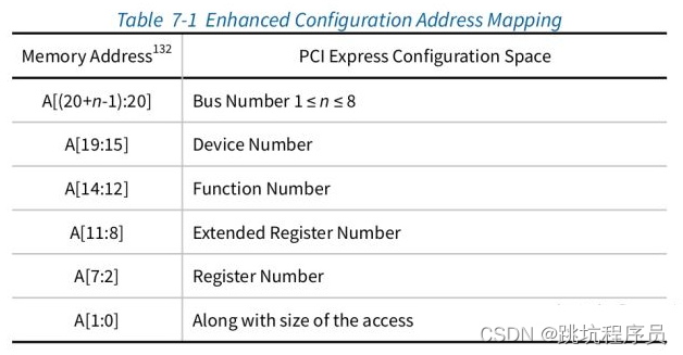
ECAM是访问PCIe配置空间一种机制,PCIe配置空间大小是4kbyte寄存器地址空间。通过扩展地址的形式把高位地址直接作为设备的Bus Number和DeviceNumber可以直接对对应总线和设备进行访问。
ATU软件配置分析
//下面都是输出地址转换  //PCIE SLAVE 的地址范围   F900_0000 F9FF_FFFF
//其实这个ATU并为修改地址转换PCIE总线地址 只是区分了IO访问和MEM访问,当处理器访问SLAVE地址空间时不同区域对外不同的TLP包访问。
oa1801_pcie_write_dbi(0x300008,0xf9020000);//内部地址为 芯片PCIE SLAVE 的地址区域
oa1801_pcie_write_dbi(0x30000c,0);//64位的高32为0
oa1801_pcie_write_dbi(0x300010,0xf9ffffff);//Limit 地址
oa1801_pcie_write_dbi(0x300014,0xf9020000);//外部PCIE 的对应地址
oa1801_pcie_write_dbi(0x300018,0x0);//64位的高32为0
oa1801_pcie_write_dbi(0x300000,0x0);//该区域为MEM访问
oa1801_pcie_write_dbi(0x300004,0x80000000);//使能ATUoa1801_pcie_write_dbi(0x300408,0xf9010000);
oa1801_pcie_write_dbi(0x30040c,0);
oa1801_pcie_write_dbi(0x300410,0xf901ffff);
oa1801_pcie_write_dbi(0x300414,0xf9010000);
oa1801_pcie_write_dbi(0x300418,0);
oa1801_pcie_write_dbi(0x300400,0x2);//设置该部分为I/O区域访问
oa1801_pcie_write_dbi(0x300404,0x80000000);//使能ATU
初始化配置
文档中寄存器地址说明
部分带ID的寄存器的访问方式,我认为部分寄存器不是在配置空间内的是由IC设计人员指定的。
访问PCIe配置空间寄存器
【PCIe】配置空间
Capbility Pointer: PCI capbility的地址偏移, capbility用于表示pci设备支持的能力。该寄存器存放Capabilities 结构链表的头指针。在一个PCIe 设备中,可能含有多个Capability 结构,这些寄存器组成一个链表:
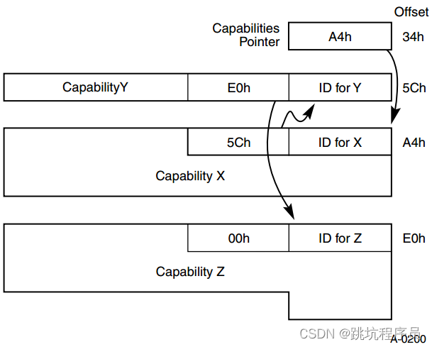
使用芯片的相关配置空间内容说明:

PCI-X和PCIe要求设备必须支持Capability结构。 在总线的基本配置空间0x40~0xFF中包含了Capability Pointer的寄存器,它存放的是Capabilities结构链表的头指针,在一个PCIe设备中可能存在多个Capability结构,这些寄存器组成一个链表。 每个Capability结构都有一个唯一的ID号,和一个指针。 指针指向下一个Capability结构,如果为0则表示到了链表的结尾。
看PCIE的寄存器文档的时候很多时候寄存器的地址(像这样 Offset: B+0x4)的描述,在文档的开头就有相关的描述:
PCI-compatible and PCI Express extended capability registers are organized into a linked list of structures
(blocks). The address of each block is configuration-dependent and cannot be computed until configuration
time in coreConsultant. In this document, register offsets within each block are specified (for example
B+0x04, where B+ indicates that 0x04 is an offset within the block); but the starting location of each block
must be found by traversing the linked list in software after configuration. The host O/S is expected to
traverse the linked list at boot time using the pointers in each block, and not the absolute address of the
blocks.
The B+ symbol appearing in the Offset value (as in Offset: B+0x4) indicates an address offset relative to the
capability base address. However, when you configure the core in coreConsultant, all parameters are
evaluated completely; and the resulting Offsets in the IP-XACT and coreConsultant GUI reports are
absolute, and not relative values.
PCI 兼容和 PCI Express 扩展能力寄存器被组织成一个链表结构(块)。 每个块的地址取决于配置,直到配置才能计算在 coreConsultant 的时间。 在本文档中,指定了每个块内的寄存器偏移量(例如B+0x04,其中B+表示0x04是块内的偏移量); 但是每个块的起始位置必须通过配置后在软件中遍历链表才能找到。 主机操作系统预计在引导时使用每个块中的指针遍历链表,而不是块的绝对地址块。出现在偏移值中的 B+ 符号(如偏移:B+0x4)表示相对于
能力基地址。 但是,当您在 coreConsultant 中配置核心时,所有参数都是完全评估; IP-XACT 和 coreConsultant GUI 报告中产生的偏移量为绝对值,而不是相对值。
Most of the implementation-specific registers (not defined by the PCI-SIG PCIe specification) are located in the Port Logic space beginning at 0x700.Going forward from release 4.40a, all new implementation-specific register groups are implemented as VSEC’s in the PCIe Extended Capability Structure address space.
大多数特定于实现的寄存器(未由 PCI-SIG PCIe 规范定义)位于从 0x700 开始的端口逻辑空间中。从版本 4.40a 开始,所有新的特定于实现的寄存器组都在 PCIe 中实现为 VSEC 扩展能力结构地址空间。
Vendor Specific Extended Capability
从LINUX的驱动设置可以推断0x700-0xc20 地址段的描述。 DWC_PCIE_DSP/PF0_PORT_LOGIC Registers 章节描述这个部分的地址是固定在0X700的固定逻辑空间。

/* Synopsys-specific PCIe configuration registers */
#define PCIE_PORT_LINK_CONTROL		0x710
#define PCIE_LINK_WIDTH_SPEED_CONTROL	0x80C
#define PCIE_MSI_ADDR_LO		0x820
#define PCIE_MSI_ADDR_HI		0x824
#define PCIE_MSI_INTR0_ENABLE		0x828
#define PCIE_MSI_INTR0_MASK		0x82C
#define PCIE_MSI_INTR0_STATUS		0x830
#define PCIE_ATU_VIEWPORT		0x900
#define PCIE_ATU_CR1			0x904
#define PCIE_ATU_CR2			0x908
#define PCIE_ATU_LOWER_BASE		0x90C
#define PCIE_ATU_UPPER_BASE		0x910
#define PCIE_ATU_LIMIT			0x914
#define PCIE_ATU_LOWER_TARGET		0x918
#define PCIE_ATU_UPPER_TARGET		0x91C
#define PCIE_MISC_CONTROL_1_OFF 0x8BC _pcie_write_dbi(0x710,0x70120);//21:16 LINK_CAPABLE 0x7 (X4): x4//bit11:8 LINK_RATE // bit5:LINK_DISABLE _pcie_write_dbi(0x80c,0x10430);//bit 16 AUTO_LANE_FLIP_CTRL_EN 0x1 (ENABLE): Enable //bit12:8 NUM_OF_LANE S0x1 (_1_LANE) S0x4 (_4_LANE): 1 lane// bit7:0 FAST_TRAINING_SEQ_pcie_write_dbi(0x82c,0xffffffff);//bit 31:0 MSI_CTRL_INT_0_EN 使能中断_pcie_write_dbi(0x828,0xffffffff);//bit 31:0 MSI_CTRL_INT_0_MASK 设置中断屏蔽位,保证MSI能产生中断_pcie_read_dbi(0x8bc);//读取了MISC_CONTROL_1_OFF_pcie_write_dbi(0x8bc,0xbff41);//该寄存器后续单独介绍配置信息,该处主要是设置bit1进行RO写操作 _pcie_write_dbi(0x100010,0);//通过DBI2设置BAR0 MASK 0,禁止BAR0_pcie_write_dbi(0x10,0);//设置BAR0地址为0_pcie_read_dbi(0x8bc);_pcie_write_dbi(0x8bc,0xbff40);//退出RO写操作_pcie_read_dbi(0x8bc);_pcie_write_dbi(0x8bc,0xbff41);//该寄存器后续单独介绍配置信息,该处主要是设置bit1进行RO写操作 _pcie_write_dbi(0x14,0);//设置BAR0地址为0_pcie_read_dbi(0x8bc);_pcie_write_dbi(0x8bc,0xbff40);//退出RO写操作_pcie_read_dbi(0x8bc);_pcie_write_dbi(0x8bc,0xbff41);//该寄存器后续单独介绍配置信息,该处主要是设置bit1进行RO写操作 _pcie_read_dbi(0x3c);_pcie_write_dbi(0x3c,0x1ff);//BRIDGE_CTRL_INT_PIN_INT_LINE_REG2 2:16 看手册 15:8 INT_PIN (选择中断脚)7:0 INT_LINE _pcie_read_dbi(0x8bc);_pcie_write_dbi(0x8bc,0xbff40);//退出RO写操作_pcie_read_dbi(0x18);_pcie_write_dbi(0x18,0xff0100);//SEC_LAT_TIMER_SUB_BUS_SEC_BUS_PRI_BUS_REG //23:16 SUB_BUS从属总线编号//15:8 SEC_BUS设置Secondary Bus Number(详细功能见定义) 15:8 SEC_BUS 7:0 PRIM_BUS 波流兼容不用_pcie_read_dbi(0x4);_pcie_write_dbi(0x4,0x100107);//TYPE1_STATUS_COMMAND_REG 配置状态和控制寄存器 bit16 立即准备看后续介绍 BIT 8 使能错误报告功能BIT 2:0 使能IO MSE BME (bus master) 该设置完成后PCIE启动了。_pcie_read_dbi(0x900);MISC_CONTROL_1_OFF 寄存器偏移地址 0x8bc介绍
bit 22 PORT_LOGIC_WR_DISABLE MISC_CONTROL_1_OFF Disable port logic register write from wire side.禁止从wire side(through the TRGT0 interface)端口逻辑寄存器写。EP模式下CFG requests are routed to TRGT0 and then to CDM through the LBC.
bit 21 P2P_ERR_RPT_CTRL Determines whether to enable Peer to Peer (P2P) error reporting.
确定是否启用对等 (P2P) 错误报告 1为启用。
bit 20 P2P_TRACK_CPL_TO_REG Determines whether to track completion of transmitted Non-Posted TLPs in P2P mode.
确定是否在 P2P 模式下跟踪传输的 Non-Posted TLP 的完成情况。1为跟踪。
bit 19:18 TARGET_ABOVE_CONFIG_LIMIT_REG Configuration requests with an address greater than CONFIG_LIMIT_REG are directed to either ELBI or TRGT1 interface based on the setting of this field.
根据该字段的设置,地址大于 CONFIG_LIMIT_REG 的配置请求将被定向到 ELBI 或 TRGT1 接口。0x1: ELBI 0x2: TRGT1。
本程序设置为0X2
bit 17:8 CONFIG_LIMIT_REG Configuration requests are directed either to CDM or ELBI/RTRGT1 based on the value of this field.
设置配置寄存器的范围,大于该范围的地址访问将变为 ELBI或RTRGT1的访问操作。
本程序设置为0X2FF
bit 7 CFG_TLP_BYPASS_EN_REG Setting of this field defines how to decide the destination of Configuration requests.
该字段的设置定义了如何决定配置请求的目的地。
设置1 Configuration TLPs are routed according to the setting of TARGET_ABOVE_CONFIG_LIMIT_REG, regardless the value of CONFIG_LIMIT_REG.
配置TLP包不理会CONFIG_LIMIT_REG。
设置0 Configuration TLPs are routed according to the setting of TARGET_ABOVE_CONFIG_LIMIT_REG, depending on the setting of CONFIG_LIMIT_REG.
配置TLP包受CONFIG_LIMIT_REG影响。
bit 6 CPLQ_MNG_EN enables the Completion Queue Management feature.
设置完成队列管理功能 1为使能
本程序设置1
bit 5 ARI_DEVICE_NUMBER When ARI is enabled, this field enables use of the device ID.
设置为1使能ARI_DEVICE_NUMBER(什么是ARI见文章开头定义)
bit 4 DISABLE_AUTO_LTR_CLR_MSG Disable the autonomous generation of LTR clear message in upstream port.
禁止上行端口自主生成 LTR 清除报文。1是禁止
bit 3 3 SIMPLIFIED_REPLAY_TIMER Enables Simplified Replay Timer (Gen4). For more details, see “Transmit Replay” in “Transmit TLP Processing”
启用简化重传计时器 。1是使能
bit 2 UR_CA_MASK_4_TRGT1 When this field is set to ‘1’, the controller suppresses error logging, error message generation, and CPL generation for non-posted requests TLPs (with UR filtering status) forwarded to your application (that is, when DEFAULT_TARGET =1). For more details, see “Advanced Error Handling For Received TLPs” chapter of the Databook.
当该字段设置为“1”时,控制器抑制错误日志记录、错误消息生成和 CPL 生成未发布的请求 TLP(具有 UR 过滤状态)
转发到您的应用程序(即,当DEFAULT_TARGET = 1)。 有关详细信息,请参阅“高级接收到的 TLP 的错误处理”数据手册的章节。
bit 1 DEFAULT_TARGET Default target for an IO or MEM request with UR/CA/CRS received. Based on the value of this field the controller either drops or forwards these requests to your application. For more details, see “ECRC Handling” and “Request TLP Routing Rules” in “Receive Routing” section of the “Controller Operations” chapter of the Databook.
带有 UR/CA/CRS 的 IO 或 MEM 请求的默认目标已收到。 根据该字段的值,控制器要么将这些请求丢弃或转发到您的应用程序。
bit 0 DBI_RO_WR_EN Write to RO Registers Using DBI. For more details, see “Writing to Read-Only Registers” in “Register Module, LBC,
and DBI” section in the “Controller Operations” chapter of the Databook.
0x1 (SET): Your application can write to some RO and HwInit register fields through the DBI when you set this field to ‘1’.
使用 DBI 写入 RO 寄存器。设置1可以通过DBI操作一些只读和初始化寄存器。初始化时需要设置1对PCIE进行初始
本程序设置1
TYPE1_STATUS_COMMAND_REG 偏移0x4 介绍
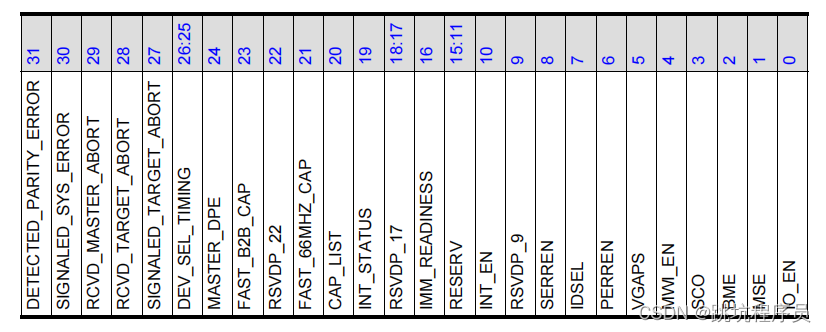
其他细节看手册
IMM_READINESS:
Immediate Readiness (optional).
立即准备(可选)。
■ When this bit is set, for accesses to this Function, software is exempt from all requirements to delay configuration accesses following any type of reset, including but not limited to the timing requirements defined in “PCI Express Reset - Rules” section of the PCI Express Base Specification.
■ 当该位置位时,对于对该功能的访问,软件免除在任何类型的复位后延迟配置访问的所有要求,包括但不限于 PCI 的“PCI Express 复位 - 规则”部分中定义的时序要求 Express 基本规范。
■ It is permitted that system software/firmware provide mechanisms that supersede the indication provided by this bit, however such software/firmware mechanisms are outside the scope of PCI Express Base Specification.
■ 允许系统软件/固件提供替代由该位提供的指示的机制,但是此类软件/固件机制超出了 PCI Express 基本规范的范围。
DMA
我使用DSP和
DMA的基地址
pcie_base_addr 应该是F9000000
#define PF0_DMA_CAP_BaseAddress 0x380000+pcie_base_addr
#define DMA_READ_ENGINE_EN_OFF (PF0_DMA_CAP_BaseAddress + 0x2c)
#define DMA_READ_INT_MASK_OFF (PF0_DMA_CAP_BaseAddress + 0xa8)
我使用的通道写是0X200基地址,读通道是0X300基地址。
#define DMA_CH_CONTROL1_OFF_RDCH_0 (PF0_DMA_CAP_BaseAddress + 0x300)
寄存器说明见1.35 DWC_PCIE_DSP/PF0_DMA_CAP Registers说明
关于RC和EP数据发送和接收的限制条件不同
DW使用有个很有意思的现象,在测试过程中导致了走了一些弯路。
IP在做RC的时候EP使用DMA读写RC的内存基本不用进行设置就能进行通信,但是RC对EP的内存空间进行DMA读写需要进行ATU和BAR的设置才能读写。

