开发环境:
- Windows 11 家庭中文版
- Microsoft Visual Studio Community 2019
- VTK-9.3.0.rc0
- vtk-example
- 参考代码
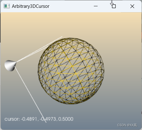
demo解决问题:允许用户使用三维光标在三维空间中定位一个点。关键类
vtkPointWidget, 光标具有轮廓边界框、轴对齐十字准线和轴阴影(轮廓和阴影可以关闭)。(可以关闭轮廓和阴影)。vtkPointWidget 和其他 3D widget 一样,具有一个很好的特点,即它可以与当前的交互样式一起工作。也就是说,如果 vtkPointWidget 没有处理事件,那么所有其他已注册的观察者(包括交互样式)都有机会处理该事件。否则,vtkPointWidget 将终止处理它所处理的事件。
主流程:(不看probe)
- 数据源1:构造一个网格化的sphereSource数据源
- 数据源2:point的位置使用cone符号化为圆锥体
- 数据源3:添加一个AddActor2D,固定在视口左下角
- 数据源4:构造3D控件pointWidget,并添加观察者myCallback,监控pointWidget交互事件
注意:point符号化的过程中,一开始是没有符号的,所以圆锥体一开始不显示,交互时间开始后设置了point的值,点背符号化后有了圆锥体,Execute中关键代码:
//获取定义该点的多边形数据(包括点)。单个点和一个顶点组成 vtkPolyData。
pointWidget->GetPolyData(this->PolyData);//给this->PolyData / point 赋值,在多个管道中间中途修改值,修改后update修改过的管道,render
this->PositionActor->SetInput(text.str().c_str());
glyph的输入我把probefilter删了,直接用point数据,也是可以相同效果的,目前没有明白为什么要加一个vtkProbeFilter,理解的帮解答下,谢谢拉!!!
另一个需要重点关注的是需要区分以下接口接口
vtkNew<vtkProbeFilter> probe;//指定一个数据对象作为输入。请注意,此方法不会建立管道连接。使用 SetInputConnection() 来 建立管道连接。probe->SetInputData(point);//输入: 此时的point值为空,需要事件内根据鼠标位置进行赋值//指定将在输入点进行探测的数据集。 //输入为输出提供几何图形(点和单元)、 而源点则通过探测(插值)生成标量、 矢量等。probe->SetSourceData(inputPolyData);//源:
参考链接1
参考链接2
参考链接3
vtkNew<vtkGlyph3D> glyph;// glyph->SetInputConnection(probe->GetOutputPort());//???不理解glyph->SetInputData(point); //此处直接使用point也可以达到效果,但是为什么非要用vtkProbeFilter 没有想通glyph->SetSourceConnection(cone->GetOutputPort());
参考链接1
参考链接2
prj name: Arbitrary3DCursor
#include <vtkActor.h>
#include <vtkCallbackCommand.h>
#include <vtkCommand.h>
#include <vtkConeSource.h>
#include <vtkGlyph3D.h>
#include <vtkNamedColors.h>
#include <vtkNew.h>
#include <vtkPointWidget.h>
#include <vtkPolyData.h>
#include <vtkPolyDataMapper.h>
#include <vtkProbeFilter.h>
#include <vtkProperty.h>
#include <vtkRenderWindow.h>
#include <vtkRenderWindowInteractor.h>
#include <vtkRenderer.h>
#include <vtkSmartPointer.h>
#include <vtkSphereSource.h>
#include <vtkTextActor.h>
#include <vtkTextProperty.h>
#include <vtkXMLPolyDataReader.h>#include <iostream>
#include <sstream>
#include <string>// This does the actual work: updates the probe.
// Callback for the interaction.
class vtkmyPWCallback : public vtkCallbackCommand
{
public:vtkmyPWCallback() = default;static vtkmyPWCallback* New(){return new vtkmyPWCallback;}virtual void Execute(vtkObject* caller, unsigned long, void*){vtkPointWidget* pointWidget = reinterpret_cast<vtkPointWidget*>(caller);//获取定义该点的多边形数据(包括点)。单个点和一个顶点组成 vtkPolyData。pointWidget->GetPolyData(this->PolyData);//给this->PolyData / point 赋值,在多个管道中间中途修改值,修改后update修改过的管道,renderdouble position[3];pointWidget->GetPosition(position);std::ostringstream text;text << "cursor: " << std::fixed << std::setprecision(4) << position[0]<< ", " << position[1] << ", " << position[2];this->PositionActor->SetInput(text.str().c_str());// this->CursorActor->VisibilityOn();std::cout << PolyData->GetNumberOfCells() << std::endl;std::cout << PolyData->GetNumberOfPoints() << std::endl;std::cout << PolyData->GetNumberOfPolys() << std::endl;}vtkPolyData* PolyData = nullptr;      //与传入的锥形有关//vtkActor* CursorActor = nullptr;    //可以不需要,如果需要控制显示隐藏状态,可以传入vtkTextActor* PositionActor = nullptr;//实时显示坐标状态
};int main(int argc, char* argv[])
{vtkSmartPointer<vtkPolyData> inputPolyData;if (argc > 1){vtkNew<vtkXMLPolyDataReader> reader;reader->SetFileName(argv[1]);reader->Update();inputPolyData = reader->GetOutput();}else{vtkNew<vtkSphereSource> sphereSource;sphereSource->SetPhiResolution(15);sphereSource->SetThetaResolution(15);sphereSource->Update();inputPolyData = sphereSource->GetOutput();}vtkNew<vtkNamedColors> colors;vtkNew<vtkPolyData> point;//https://blog.csdn.net/liushao1031177/article/details/122860254//https://blog.csdn.net/yuyangyg/article/details/78165570//https://www.cnblogs.com/ankier/p/3166210.html/*在指定点位置采样数据值vtkProbeFilter 是一个过滤器,用于计算指定点位置的点属性(如标量、矢量等)。该过滤器有两个输入:输入和源。输入的几何结构通过过滤器。通过对源数据进行插值,在输入点位置计算出点属性。例如,我们可以根据体积(源数据)计算平面(指定为输入的平面)上的数据值。源数据的单元格数据会根据每个输入点所在的源单元格复制到输出端。如果源点数据和单元格数据中都存在同名数组,则只探查点数据中的数组。该过滤器可用于重新采样数据,或将一种数据集形式转换为另一种数据集形式。例如,非结构化网格(vtkUnstructuredGrid)可以用体积(三维 vtkImageData)进行探测,然后使用体积渲染技术将结果可视化。另一个例子:可以使用一条直线或曲线来探测数据,以生成沿该直线或曲线的 x-y 图。警告vtkProbeFilter 的一个关键算法组件是其查找包含探测点的单元格的方式。默认情况下,vtkDataSet::FindCell() 方法会被使用,该方法反过来使用 vtkPointLocator 来执行加速搜索。不过,在某些情况下,使用 vtkPointLocator 可能无法识别包围单元格。更稳健但更慢的方法是使用 vtkCellLocator 执行 FindCell() 操作(通过指定 CellLocatorPrototype)。最后,可以通过指定 vtkFindCellStrategy 的实例来配置更高级的搜索。(注意:图像数据探测从不使用定位器,因为查找包含的单元格是一个简单、快速的操作。因此指定 vtkFindCellStrategy 或单元格定位器原型没有任何作用)。vtkProbeFilter 一旦找到包含查询点的单元格,就会使用单元格的插值函数来执行插值/计算点属性。vtkPointInterpolator 支持多种广义内核,而 vtkSPHInterpolator 则支持多种 SPH 内核。*/vtkNew<vtkProbeFilter> probe;//指定一个数据对象作为输入。请注意,此方法不会建立管道连接。使用 SetInputConnection() 来 建立管道连接。probe->SetInputData(point);//输入: 此时的point值为空,需要事件内根据鼠标位置进行赋值//指定将在输入点进行探测的数据集。 //输入为输出提供几何图形(点和单元)、 而源点则通过探测(插值)生成标量、 矢量等。probe->SetSourceData(inputPolyData);//源: std::cout << point->GetNumberOfCells() << std::endl;std::cout << point->GetNumberOfPoints() << std::endl;std::cout << point->GetNumberOfPolys() << std::endl;// Create glyph.vtkNew<vtkConeSource> cone;cone->SetResolution(30);//https://blog.csdn.net/jigetage/article/details/86633156//https://www.cnblogs.com/vaughnhuang/p/17584058.htmlvtkNew<vtkGlyph3D> glyph;// glyph->SetInputConnection(probe->GetOutputPort());//???不理解glyph->SetInputData(point); //此处直接使用point也可以达到效果,但是为什么非要用vtkProbeFilter 没有想通glyph->SetSourceConnection(cone->GetOutputPort());glyph->SetVectorModeToUseVector();glyph->SetScaleModeToDataScalingOff();glyph->SetScaleFactor(inputPolyData->GetLength() * 0.1);vtkNew<vtkPolyDataMapper> glyphMapper;glyphMapper->SetInputConnection(glyph->GetOutputPort());vtkNew<vtkActor> glyphActor;glyphActor->SetMapper(glyphMapper);glyphActor->VisibilityOn();//point为空,没有glyph显示vtkNew<vtkPolyDataMapper> mapper;mapper->SetInputData(inputPolyData);vtkNew<vtkActor> actor;actor->SetMapper(mapper);actor->GetProperty()->SetRepresentationToWireframe();actor->GetProperty()->SetColor(colors->GetColor3d("gold").GetData());vtkNew<vtkTextActor> textActor;textActor->GetTextProperty()->SetFontSize(12);textActor->SetPosition(10, 20);textActor->SetInput("cursor:");textActor->GetTextProperty()->SetColor(colors->GetColor3d("White").GetData());// Create the RenderWindow, Render1er and both Actors.vtkNew<vtkRenderer> ren1;vtkNew<vtkRenderWindow> renWin;renWin->AddRenderer(ren1);vtkNew<vtkRenderWindowInteractor> iren;iren->SetRenderWindow(renWin);// The SetInteractor method is how 3D widgets are associated with the render// window interactor. Internally, SetInteractor sets up a bunch of callbacks// using the Command/Observer mechanism (AddObserver()).vtkNew<vtkmyPWCallback> myCallback;myCallback->PolyData = point;//myCallback->PolyData = inputPolyData;//myCallback->CursorActor = glyphActor;myCallback->PositionActor = textActor;// The point widget is used probe the dataset.vtkNew<vtkPointWidget> pointWidget;pointWidget->SetInteractor(iren);pointWidget->SetInputData(inputPolyData);//指定移动范围pointWidget->AllOff();pointWidget->PlaceWidget();pointWidget->AddObserver(vtkCommand::InteractionEvent, myCallback);ren1->AddActor(glyphActor);ren1->AddActor(actor);ren1->AddActor2D(textActor);//2D actor// Add the actors to the renderer, set the background and size.ren1->GradientBackgroundOn();ren1->SetBackground(colors->GetColor3d("SlateGray").GetData());ren1->SetBackground2(colors->GetColor3d("Wheat").GetData());renWin->SetSize(300, 300);renWin->SetWindowName("Arbitrary3DCursor");renWin->Render();pointWidget->On();// Render the imageiren->Initialize();renWin->Render();iren->Start();return EXIT_SUCCESS;
}